


Left
Component
Description
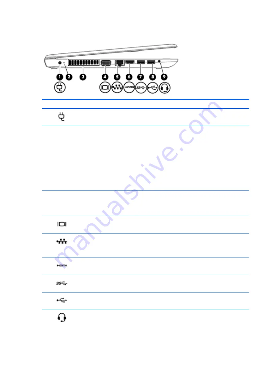
(1)
Power connector
Connects an AC adapter.
(2)
Battery light
When AC power is connected:
●
White: The battery charge is greater than 90 percent.
●
Amber: The battery charge is from 0 to 90 percent.
●
Off: The battery is not charging.
When AC power is disconnected (battery not charging):
●
Blinking amber: The battery has reached a low battery
level. When the battery has reached a critical battery level,
the battery light begins blinking rapidly.
●
Off: The battery is not charging.
(3)
Vent
Enables airflow to cool internal components.
NOTE:
The computer fan starts up automatically to cool
internal components and prevent overheating. It is normal for
the internal fan to cycle on and off during routine operation.
(4)
External monitor port
Connects an external VGA monitor or projector.
(5)
RJ-45 (network) jack/lights
Connects a network cable.
●
Green (left): The network is connected.
●
Amber (right): The network is showing activity.
(6)
HDMI port
Connects an optional video or audio device, such as a high-
definition television, any compatible digital or audio component,
or a high-speed HDMI device.
(7)
USB 3.0 port
Connects an optional USB device, such as a keyboard, mouse,
external drive, printer, scanner or USB hub.
(8)
USB 2.0 port
Connects an optional USB device, such as a keyboard, mouse,
external drive, printer, scanner or USB hub.
(9)
Audio-out (headphone)/Audio-in (microphone)
combo jack
Connects optional powered stereo speakers, headphones,
earbuds, a headset, or a television audio cable. Also connects an
optional headset microphone. This jack does not support
optional microphone-only devices.
6
Chapter 2 External component identification
Содержание mt245
Страница 4: ...iv Safety warning notice ...
Страница 8: ...viii ...
Страница 26: ...18 Chapter 3 Illustrated parts catalog ...
Страница 64: ...56 Chapter 5 Removal and replacement procedures for Authorized Service Provider parts ...
Страница 70: ...62 Chapter 6 Computer Setup BIOS and MultiBoot ...
Страница 72: ...64 Chapter 7 Device management ...
Страница 76: ...68 Chapter 8 Diagnostics and Troubleshooting ...
Страница 80: ...72 Chapter 10 Adding an Image Restore Tool ...
Страница 88: ...80 Chapter 12 Statement of Volatility ...
Страница 92: ...84 Chapter 13 Power cord set requirements ...
Страница 94: ...86 Chapter 14 Recycling ...
Страница 98: ...90 Index ...


