564
Configuring other voice functions
Select
Voice Management
>
Local Number
from the navigation tree, and then click the icon of the
local number to be configured to access the call services configuration page as shown in
.
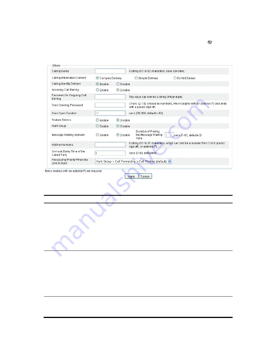
Figure 585
Call services configuration page
Table 214
Configuration items
Item Description
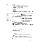
Calling Name
Set the calling name, a string of case-sensitive characters including numbers 0 through 9,
letters A through Z or a through z, underlines (_), hyphens (-),dots (.), exclamation point
(!), percent sign (%), asterisk (*), plus sign (+), grave accent (`), single quotation mark ('),
and tilde (~).
By default, no calling name is configured.
The calling name in the calling identity information can only be transmitted in MDMF
format. Therefore, if the calling information delivery is enabled, you must select the
Complex Delivery
option in the
Calling Information Delivery
area.
Calling Information
Delivery
Configure the format of calling information:
•
Complex Delivery
—Calling identity information is transmitted in complex format.
•
Simple Delivery
—Calling identity information is transmitted in simple format.
•
Do Not Delivery
—Do not deliver the Calling identity information.
By default, the complex delivery is adopted.
If the remote end supports one format only, you must use the same message format at the
local end.
Call Identity
Delivery
•
Enable.
•
Disable.
The calling identity is delivered by default.
Содержание MSR SERIES
Страница 17: ...xv Documents 835 Websites 835 Conventions 836 Index 838 ...
Страница 20: ...3 Figure 3 Initial page of the Web interface ...
Страница 42: ...25 Figure 13 Firefox Web browser setting ...
Страница 59: ...42 Figure 27 Checking the basic service configuration ...
Страница 73: ...56 Figure 35 Sample interface statistics ...
Страница 156: ...139 Figure 139 Rebooting the 3G modem ...
Страница 168: ...151 Figure 152 Configuring Web server 2 ...
Страница 174: ...157 Figure 158 Configure the URL filtering function ...
Страница 187: ...170 Upon detecting the Land or Smurf attack on Ethernet 0 2 Router outputs an alarm log and drops the attack packet ...
Страница 242: ...225 Figure 233 Enabling the DHCP client on interface Ethernet 0 1 ...
Страница 247: ...230 Figure 236 The page for configuring an advanced IPv4 ACL ...
Страница 255: ...238 Figure 241 Advanced limit setting ...
Страница 298: ...281 e Click Apply 2 Configure Router B in the same way Router A is configured ...
Страница 354: ...337 Figure 339 Configuring a login control rule so Host B cannot access Router through the Web ...
Страница 400: ...383 Figure 387 Verifying the configuration ...
Страница 405: ...388 ...
Страница 523: ...506 Figure 530 Ping configuration page ...
Страница 538: ...521 a Click Device A on the topology diagram b Click Ethernet 0 2 on the panel diagram c Click Port Guard ...
Страница 744: ...727 Verifying the configuration In the case that the IP network is unavailable calls can be made over PSTN ...
Страница 775: ...758 Figure 785 Configuring a jump node ...
Страница 791: ...774 Figure 801 Configuring a jump node ...


