316
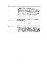
Item Description
Protection
Type
Set the type of protection enabled on the port:
•
Not Set
—No protection is enabled on the port.
•
Edged Port, Root Protection, Loop Protection
—For more information, see
.
Point to Point
Specify whether the port is connected to a point-to-point link:
•
Auto
—Automatically detects whether the link type of the port is point-to-point.
•
Force False
—Specifies that the link type for the port is not point-to-point link.
•
Force True
—Specifies that the link type for the port is point-to-point link.
Transmit Limit
Configure the maximum number of MSTP packets that can be sent during each Hello
interval.
The larger the transmit limit is, the more network resources will be occupied. HP
recommends you to use the default value.
mCheck
In a switched network, if a port on an MSTP device connects to an STP device, this port
will automatically migrate to the STP-compatible mode. However, after the STP device is
removed, whether the port on the MSTP device can migrate automatically to the MSTP
mode depends on which of the following parameter is selected:
•
Enable
—Performs mCheck. The port automatically migrates back to the MSTP mode.
•
Disable
—Does not perform mCheck. The port does not automatically migrate back
to the MSTP mode.
Instance
•
Instance ID
—Set the MSTI ID.
•
Port Priority
—Set the priority of the port in the current MSTI. The priority of a port is
an import factor in determining whether the port can be elected as the root port.
•
Path Cost
—Select to calculate the path cost automatically or set the path cost
manually.
Table 145
Protection types
Protection type Description
Edged Port
Configure the port as an edge port.
Some ports of access layer devices are directly connected to PCs or file servers,
which cannot generate BPDUs. You can set these ports as edge ports to achieve fast
transition for these ports.
HP recommends you to enable the BPDU guard function in conjunction with the
edged port function to avoid network topology changes when the edge ports receive
configuration BPDUs.
Root Protection
Enable the root guard function.
Configuration errors or attacks might result in configuration BPDUs with their
priorities higher than that of a root bridge, which causes a new root bridge to be
elected and network topology change to occur. The root guard function is used to
address such a problem.
Loop Protection
Enable the loop guard function.
By keeping receiving BPDUs from the upstream device, a device can maintain the
state of the root port and other blocked ports. These BPDUs might get lost because of
network congestion or unidirectional link failures. The device will re-elect a root port,
and blocked ports might transit to the forwarding state, causing loops in the
network. The loop guard function is used to address such a problem.
Содержание MSR SERIES
Страница 17: ...xv Documents 835 Websites 835 Conventions 836 Index 838 ...
Страница 20: ...3 Figure 3 Initial page of the Web interface ...
Страница 42: ...25 Figure 13 Firefox Web browser setting ...
Страница 59: ...42 Figure 27 Checking the basic service configuration ...
Страница 73: ...56 Figure 35 Sample interface statistics ...
Страница 156: ...139 Figure 139 Rebooting the 3G modem ...
Страница 168: ...151 Figure 152 Configuring Web server 2 ...
Страница 174: ...157 Figure 158 Configure the URL filtering function ...
Страница 187: ...170 Upon detecting the Land or Smurf attack on Ethernet 0 2 Router outputs an alarm log and drops the attack packet ...
Страница 242: ...225 Figure 233 Enabling the DHCP client on interface Ethernet 0 1 ...
Страница 247: ...230 Figure 236 The page for configuring an advanced IPv4 ACL ...
Страница 255: ...238 Figure 241 Advanced limit setting ...
Страница 298: ...281 e Click Apply 2 Configure Router B in the same way Router A is configured ...
Страница 354: ...337 Figure 339 Configuring a login control rule so Host B cannot access Router through the Web ...
Страница 400: ...383 Figure 387 Verifying the configuration ...
Страница 405: ...388 ...
Страница 523: ...506 Figure 530 Ping configuration page ...
Страница 538: ...521 a Click Device A on the topology diagram b Click Ethernet 0 2 on the panel diagram c Click Port Guard ...
Страница 744: ...727 Verifying the configuration In the case that the IP network is unavailable calls can be made over PSTN ...
Страница 775: ...758 Figure 785 Configuring a jump node ...
Страница 791: ...774 Figure 801 Configuring a jump node ...

