


255
Figure 255
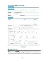
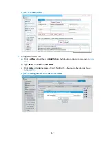
Creating an SNMP view (2)
describes the configuration items for creating an SNMP view. After configuring the parameters
of a rule, click
Add
to add the rule into the list box at the lower part of the page. After configuring all rules,
click
Apply
to create an SNMP view. The view will not be created if you click
Cancel
.
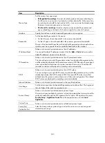
Table 123
Configuration items
Item Description
View Name
Set the SNMP view name.
Rule
Select to exclude or include the objects in the view range determined by
the MIB subtree OID and subtree mask.
MIB Subtree OID
Set the MIB subtree OID (such as 1.4.5.3.1) or name (such as system).
MIB subtree OID identifies the position of a node in the MIB tree, and it can
uniquely identify a MIB subtree.
Subtree Mask
Set the subtree mask.
If no subtree mask is specified, the default subtree mask (all Fs) will be used
for mask-OID matching.
Adding rules to an SNMP view
Click the
icon corresponding to the specified view on the page as shown in
. The
Add rule
for the view ViewDefault
window appears as shown in
. After configuring the parameters,
click
Apply
to add the rule for the view.
describes the configuration items for creating an
SNMP view.
Содержание MSR SERIES
Страница 17: ...xv Documents 835 Websites 835 Conventions 836 Index 838 ...
Страница 20: ...3 Figure 3 Initial page of the Web interface ...
Страница 42: ...25 Figure 13 Firefox Web browser setting ...
Страница 59: ...42 Figure 27 Checking the basic service configuration ...
Страница 73: ...56 Figure 35 Sample interface statistics ...
Страница 156: ...139 Figure 139 Rebooting the 3G modem ...
Страница 168: ...151 Figure 152 Configuring Web server 2 ...
Страница 174: ...157 Figure 158 Configure the URL filtering function ...
Страница 187: ...170 Upon detecting the Land or Smurf attack on Ethernet 0 2 Router outputs an alarm log and drops the attack packet ...
Страница 242: ...225 Figure 233 Enabling the DHCP client on interface Ethernet 0 1 ...
Страница 247: ...230 Figure 236 The page for configuring an advanced IPv4 ACL ...
Страница 255: ...238 Figure 241 Advanced limit setting ...
Страница 298: ...281 e Click Apply 2 Configure Router B in the same way Router A is configured ...
Страница 354: ...337 Figure 339 Configuring a login control rule so Host B cannot access Router through the Web ...
Страница 400: ...383 Figure 387 Verifying the configuration ...
Страница 405: ...388 ...
Страница 523: ...506 Figure 530 Ping configuration page ...
Страница 538: ...521 a Click Device A on the topology diagram b Click Ethernet 0 2 on the panel diagram c Click Port Guard ...
Страница 744: ...727 Verifying the configuration In the case that the IP network is unavailable calls can be made over PSTN ...
Страница 775: ...758 Figure 785 Configuring a jump node ...
Страница 791: ...774 Figure 801 Configuring a jump node ...


