HP M34D Скачать руководство пользователя страница 13

11 


How to order parts 

The HP authorized repair center can purchase the power board from HP. 

Power board 

Description 

HP spare part number 

Manufacturer part number 

PSU M34D 

N12315-001 

PLPCKL482UQB2 

Capacitors and connectors are available for purchase from the following EU distributors: 


Farnell:  

Farnell UK - Electronic Components Distributor


RS Component:  

Capacitors | RS Components (rs-online.com)


United Chemi-Con: 

Digikey Electronics


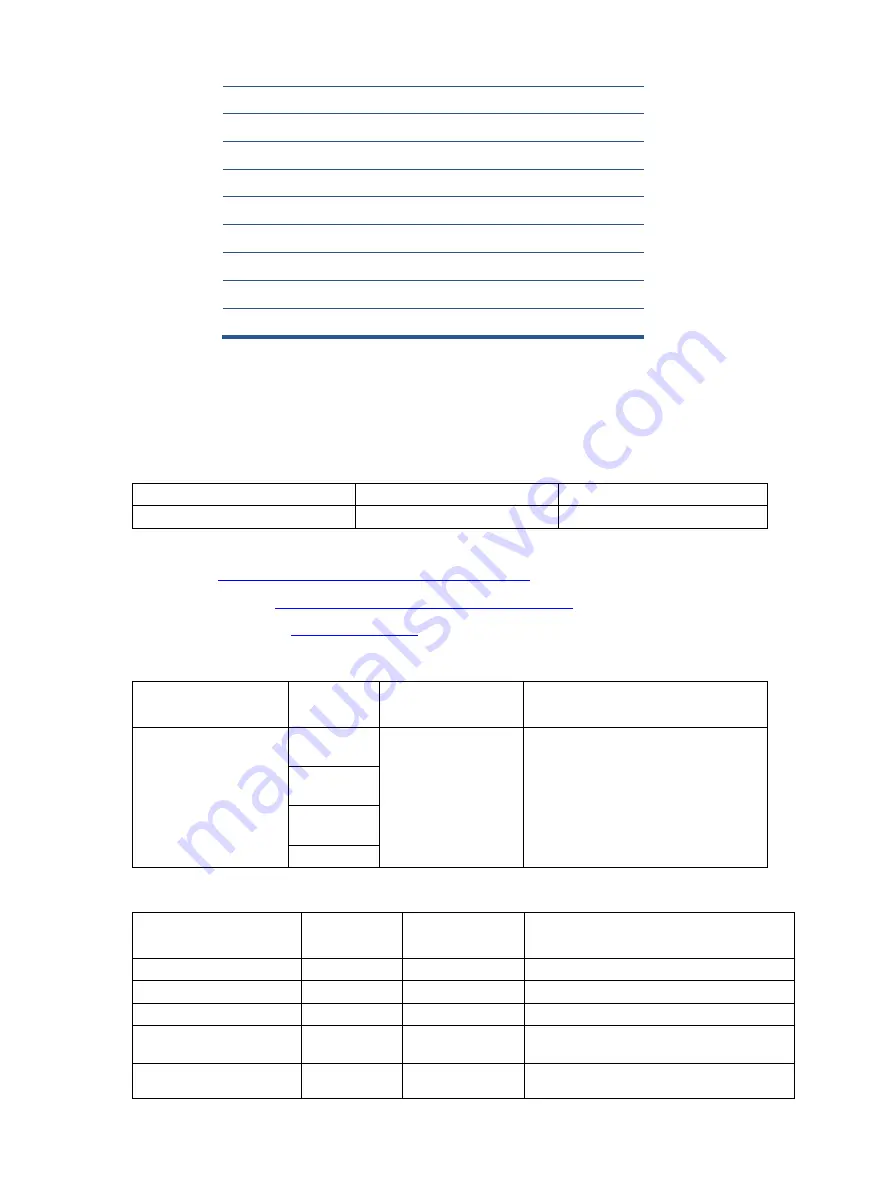
Capacitors by distributor 

Component 
description 

Location 

Component 
distributor 

Distributor part number 

EC 680uF 20% 35V 

12.5*20 3000 hr 2A 

ENB1 

C9102 

United Chemi-Con 

EGPA350ELL681MK20S 

C9104 

C9103 

C9130 

Connectors by manufacturer 

Component 
description 

Location 
identifier 

Component 
distributor 

Distributer part number 

HDMI 

CN501 

RS 

SD-47151-001(Molex) 

DisplayPort 

CN503 

Farnell 

DP1RD20JQ3(JAE) 

USB Type-C 

CN5101 

RS 

DX07S024JJ2R130(JAE


USB B TYPE 

CN1001 

RS 

 692221030100 

(Wurth Elektronik


USB 3.0 

CN1004 

CN1005 

Farnell 

48406-0001(MOLEX


13 

KEY_FRAME 

1


14 

REAR COVER 

1


15 

STAND ASS'Y 

1


16 

BASE_ASS’Y  

1


17 

0M1G3030  4120 

13 

18 

0M1G1030  6120 

10 

19 

QM1G38400601200ARA 

20 

0Q1G1030  6120 

21 

0M1G2940 10 47 CR3 


Содержание M34D

Страница 1: ...Maintenance and Service Guide M34D model SUMMARY This guide provides information about spare parts removal and replacement of parts diagnostic tests problem troubleshooting and more ...

Страница 2: ...d States and other countries The information contained herein is subject to change without notice The only warranties for HP products and services are set forth in the express warranty statements accompanying such products and services Nothing herein should be construed as constituting an additional warranty HP shall not be liable for technical or editorial errors or omissions contained herein Fir...

Страница 3: ...4 Front components 6 Rear components 7 Locating the serial number and product number 9 3 Illustrated parts catalog 10 How to order parts 11 4 Removal and replacement procedures 13 Preparation for disassembly 13 Rear Cover 13 Power board 15 Connector repair 16 Audio connector CN605 17 HDMI connector CN501 18 DP connector CN503 18 TYPE C connector CN5101 19 USB B TYPE connector CN1001 20 USB3 0 conn...

Страница 4: ...lectrical components are sensitive to electrostatic discharge ESD Follow ESD safety procedures while handling these parts Some products contain more than one battery Do not disassemble or expose a battery to high temperatures such as throwing into fire or the battery may explode Refer to government requirements for battery recycling or disposal This information provides general service information...

Страница 5: ...ctive is a legal requirement by the EU European Union for the global electronics industry sold in the EU and other countries Any electrical and electronics products launched in the market after June 2006 should meet this RoHS requirement Products launched in the market before June 2006 are not required to be compliant with RoHS parts If the original parts are not RoHS complaint the replacement par...

Страница 6: ...tments in several languages for easy setup and screen optimization Color space presets for Neutral 6500 Energy saver feature to meet requirements for reduced power consumption Security cable slot on the rear of the monitor for an optional security cable Cable management feature for placement of cables and cords DisplayPort video input cable included High Definition Multimedia Interface HDMI video ...

Страница 7: ...information refer to the Product Notices provided in your documentation kit To access the latest user guides or manuals for your product go to http www hp com support and follow the instructions to find your product Then select Manuals ...

Страница 8: ...ents on the front of the monitor use this illustration and table Table 1 1 Front components and their descriptions Component Function 1 Power light White The monitor is turned on Amber Monitor is in a reduced power state because of inactivity ...

Страница 9: ...s in the On position to turn on the monitor 4 Master power switch Turns the monitor on or off 5 Power connector Connects the power cord 6 HDMI port Connects the HDMI cable to a source device such as a computer or game console 7 DisplayPort connector Connects the DisplayPort cable to a source device such as a computer or game console 8 USB Type C port upstream Connects a USB Type C cable to a sourc...

Страница 10: ...1 USB port Connects a USB device provides high speed data transfer and for select products charges small devices when the computer is on or in Sleep mode 12 USB port 2 Connects a USB device provides high speed data transfer and for select products charges small devices when the computer is on or in Sleep mode with OSD Performance mode on 13 Audio out headphone Connects optional powered stereo spea...

Страница 11: ...oduct number The SPEC label is located on the rear of the monitor The serial number and product number are located on a Safety label You may need these numbers when contacting HP about the monitor model For worldwide models except India ...

Страница 12: ...ify the monitor major components use this illustration and table Item Description Qty 1 PANEL 1 2 MIDDLE_FRAME 1 3 LENS 1 4 SPONGE 1 5 MYLAR 1 6 POWER BOARD 1 7 MAIN BOARD 1 8 MAIN FRAME 1 9 MYLAR 1 10 LED BOARD 1 11 SPEAKER 2 12 KEY BOARD 1 ...

Страница 13: ...escription Location Component distributor Distributor part number EC 680uF 20 35V 12 5 20 3000 hr 2A ENB1 C9102 United Chemi Con EGPA350ELL681MK20S C9104 C9103 C9130 Connectors by manufacturer Component description Location identifier Component distributor Distributer part number HDMI CN501 RS SD 47151 001 Molex DisplayPort CN503 Farnell DP1RD20JQ3 JAE USB Type C CN5101 RS DX07S024JJ2R130 JAE USB ...

Страница 14: ...se cables from the HP part store at https partsurfer hp com Search aspx Internal and External Power Supplies are available for purchase from the following EU distributor EET https www eetgroup com en eu NOTE HP continually improves and changes product parts For complete and current information about supported parts for your product go to https partsurfer hp com Search aspx select your country or r...

Страница 15: ... of this guide 2 Clean the room for disassembly 3 Identify the disassembly area 4 Check the position that the monitors are to be placed along with the number of monitors Prepare the area for material flow according to the disassembly layout 5 Be sure to have the following equipment and materials Press fixture Working table Screwdriver Knife Gloves Cleaning cloth ESD protection Scraper bar in the f...

Страница 16: ...e and rear case 3 Insert the scraper bar tool into the gap between the middle frame and rear case and then rotate The hook opens Repeat the steps 4 Lift the rear cover and remove the key board wire and speaker wire from the interface board 5 Disassemble the Key board and LED board from the Rear Cover if required 6 Remove 2 screws from the bracket ...

Страница 17: ...PLPCKL482UQB2 Before removing the power board follow these steps Prepare the monitor for disassembly See Preparation for disassembly on page 13 Remove the power board 1 The HP M34D power board connector position is as follows 2 Locate the part number location on the board Warning After unplugging the power supply the capacitance is still charged do not touch and discharge the capacitor ...

Страница 18: ...n the main board board part number CBPCPD9H1Q1 The connector s identifiers are as follows Connector Location HDMI CN501 DisplayPort CN503 USB Type C CN5101 USB B TYPE CN1001 USB 3 0 CN1004 CN1005 Audio CN605 Before repairing connectors follow these steps Prepare the monitor for disassembly See Preparation for disassembly on page 13 ...

Страница 19: ...ction of the circuit board revealed look in good condition After repaired must connect source to each port to check Main board function is ordinary Note The requirement of professional repairers regulation by ERP lot5 1 The professional repairer has the technical competence to repair electronic displays and complies with the applicable regulations for repairers of electrical equipment in the Membe...

Страница 20: ... the solder on the pins 3 Lift the CN501 connector from the circuit board 4 Place the new component on the circuit board Be sure that it matches the footprint 5 Solder the new component DP connector CN503 Repair the DP connector 1 Use a soldering iron and a de soldering pump to remove as much solder as possible from the pin 2 Use a hot air gun to melt the solder on the pins ...

Страница 21: ...t TYPE C connector CN5101 Repair the TYPE C connector 1 Use a soldering iron and a de soldering pump to remove as much solder as possible from the pin 2 Use a hot air gun to melt the solder on the pins 3 Lift the CN5101 connector from the circuit board 4 Place the new component on the circuit board Be sure that it matches the footprint 5 Solder the new component ...

Страница 22: ...n the circuit board Be sure that it matches the circuit board footprint 4 Solder the new component USB3 0 connector CN1004 CN1005 Repair the USB 3 0 connector 1 Use a soldering iron and a de soldering pump to remove as much solder as possible from the pin 2 Lift the CN1004 CN1005 connector from the PCB 3 Place the new component on the circuit board Be sure that it matches the circuit board footpri...

Страница 23: ...er DP test Confirm whether image displays and sound plays correctly on the monitor Computer or DVD player USB C test Confirm whether image displays and sound plays correctly on the monitor Computer or USB C player Audio test Change volume and balance to confirm whether volume is smooth and loud enough Speaker Table 4 2 Solving common problems Problem Possible cause Solution Screen is blank or vide...

Страница 24: ... Input Signal Out of Range is displayed on screen Video resolution and or refresh rate are set higher than what the monitor supports Change the settings to a supported setting The monitor does not enter into a low power sleep state The monitor s power saving control is disabled Open the OSD menu and select Power select Auto Sleep Mode and then set auto sleep to On On Screen Menus are Locked is dis...

Страница 25: ...wer board removal 15 power connector location 7 power light location 6 precautions 2 preparation for disassembly 13 RC removal 13 rear components 7 removal power board 15 RC 13 removal and replacement procedures 13 returning to customer 3 RoHS 2002 95 EC requirements 3 safety information 2 serial number location 9 service information 2 spare parts 10 support and troubleshooting 21 troubleshooting ...

Отзывы: