background image

Connecting multiple displays with Tile Mode

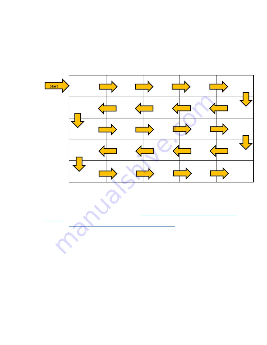
The recommended cable routing for daisy chain in Tile Mode is to start with the upper left display and
connect across the upper tier of displays going from left to right to the last display in that tier. Then
cable from the upper right display to the display just below it and connect across from right to left to
the last display on the left. Continue this back and forth, top to bottom cable route for all the tiers in
the wall as indicated in the next figure.

Figure 3-33

  Recommended cable routing for Tile Mode

Multiple displays (up to 25) may be connected to a single media player/computer using Tile Mode.
Multiple displays in Tile Mode are only supported with either DisplayPort or VGA video input sources.
When connecting the multiple displays, the media player/computer is connected to the first display
only with either a DisplayPort or VGA connection to the media player/computer. All the subsequent
displays are connected to each other via daisy chain using either the DP OUT connector from one
display to the DP IN connector of the next display (

Figure 3-35 Daisy chain connection – DisplayPort

on page 25

), or using the VGA OUT connector from one display to the VGA IN connector of the

next display (

Figure 3-36 Daisy chain connection -- VGA on page 25

). All displays must be

connected with the same video source, either DisplayPort or VGA. When using Tile mode to connect
multiple displays, only one desktop image may be displayed across all the tiled displays

24

Chapter 3   Setting up the display

ENWW

Содержание LD4730

Страница 1: ...HP LD4730 and LD4730G LCD Ultra slim Bezel Digital Signage Displays User Guide ...

Страница 2: ...y HP shall not be liable for technical or editorial errors or omissions contained herein This document contains proprietary information that is protected by copyright No part of this document may be photocopied reproduced or translated to another language without the prior written consent of Hewlett Packard Company Microsoft Windows and Windows Vista are either trademarks or registered trademarks ...

Страница 3: ...ecifications WARNING Text set off in this manner indicates that failure to follow directions could result in bodily harm or loss of life CAUTION Text set off in this manner indicates that failure to follow directions could result in damage to equipment or loss of information NOTE Text set off in this manner provides important supplemental information ENWW iii ...

Страница 4: ...iv About this guide ENWW ...

Страница 5: ...g up the remote control 11 Mounting a single display on a stand Sold Separately 12 Installing the HP LD4730 Frame System Sold Separately 12 Securing the display 15 Connecting cables 15 Connecting multiple displays to one player 22 Connecting multiple displays with Video Over Ethernet VOE 22 Connecting multiple displays with Tile Mode 24 Mounting the display 27 Mounting in portrait position 28 Cons...

Страница 6: ...bleshooting 52 Solving common problems 52 Using Online Technical Support 53 Preparing to call technical support 54 Appendix B Technical specifications 55 HP Digital Signage Display 55 Recognizing preset display resolutions 57 Preset display modes 57 High definition video formats 58 Display quality and pixel policy 59 Power indicator 59 Appendix C Agency regulatory notices 60 Federal Communications...

Страница 7: ...vironmental notices 63 Disposal of waste equipment by users in private households in the European Union 63 Chemical substances 63 HP recycling program 63 Restriction of Hazardous Substances RoHS 63 Turkey EEE regulation 64 Ukraine Restriction of Hazardous Substances 64 ENWW vii ...

Страница 8: ...viii ENWW ...

Страница 9: ...nd good visibility in any light Local dimming for enhanced contrast in dark areas of the image On Screen Display OSD menu in several languages for ease of setup and screen optimization Screen adjustment buttons Power On Off OSD Controls MENU and INPUT on the back of the display Management software for stand alone displays on or off a network DDC CI interface to allow control of the display from an...

Страница 10: ...DisplayPort cable RGB VGA cable External infrared sensor Infrared daisy chain cable Optional accessories The following can be purchased separately Stand kit Speakers kit HP LD4730 Frame System HP DreamColor Display Calibration Solution 2 Chapter 1 Product features ENWW ...

Страница 11: ...r connect all power cords for the media player computer and its peripheral devices such as a display printer scanner to some form of surge protection device such as a power strip or Uninterruptible Power Supply UPS Not all power strips provide surge protection the power strips must be specifically labeled as having this ability Use a power strip whose manufacturer offers a Damage Replacement Polic...

Страница 12: ...ay the same static image on the screen for prolonged periods of time To avoid burn in or image sticking and to prolong the life of the display you should activate one of the four ISM selections in the OSD activate a screen saver application periodically cycle between static information and moving images or turn off the display when it is not in use for prolonged periods of time Slots and openings ...

Страница 13: ...leaner directly on the screen surface It might seep behind the bezel and damage the electronics CAUTION To clean the display screen or cabinet do not use cleaners that contain any petroleum based materials such as benzene or thinner or any volatile substance These chemicals might damage the display Cleaning the LD4730G The protective glass on the LD4730G is extremely easy to clean Most marks wipe ...

Страница 14: ...ing on a media player computer The HP Network Sign Manager is designed for this purpose Displays can be set up in a tiled array See Using Tile Mode on page 44 for details The external IR sensor is particularly helpful for displays mounted in an array Displays can be connected by their IR ports with the IR daisy chain Cable and be controlled either as a group or singularly using the remote control ...

Страница 15: ...1 1 3 7 6 5 4 2 2 3 Table 3 1 Major components Component Function 1 Speaker installation 4 holes 2 Stand installation 4 holes 3 Handles 4 4 Control panel with power and OSD navigation buttons 5 Power and data connectors 6 Remote control sensor and ambient light sensor 7 Security cable provision ENWW Identifying display components 7 ...

Страница 16: ... D3 x 12 mm 0 47 in screws to secure the speakers to the display Figure 3 3 Securing the speakers to the display 3 After installing the speakers connect to the SPEAKER input terminal by connecting the proper color match for the left and right speakers Figure 3 4 Connecting to the input terminal 8 Chapter 3 Setting up the display ENWW ...

Страница 17: ...A DisplayPort VOE when not in OSD Accept Save a highlighted OSD choice when in OSD 2 MENU Invoke the On Screen Display Menu Select highlighted entry Exit OSD 3 Select Adjust OSD choice navigate down 4 Select Adjust OSD choice navigate up 5 Select Adjust OSD choice navigate left 6 Select Adjust OSD choice navigate right 7 Power display ON or OFF 8 Power status Green Full Power Red Stand by mode OFF...

Страница 18: ... enter zero second time to enter a space Period Decimal point or period DEL Back or Delete Navigates backward to the previous menu screen or delete text in text box INPUT Input Select video source VGA DisplayPort VOE EXIT Exit Exits the on screen menu Unsaved changes will be lost Up down left right arrows Allows navigation of the On Screen Display menus and adjustment of the system settings VOL Vo...

Страница 19: ...ing DP DisplayPort input select Selects DisplayPort video input source for viewing TILE Tile mode Opens the Tile Mode submenu of the OSD Color CAL Color calibration Launches the color calibration process Setting up the remote control Insert the batteries into the remote control as follows Figure 3 7 Inserting batteries 1 Slide off the battery cover 2 Insert the batteries with correct polarity 3 Cl...

Страница 20: ...plays giving the edge a finished look To frame a group of displays you need as many kits as you have displays in a row or column whichever is greater For example three kits will frame a 3 x 3 group a 3 x 1 group or a 1 x 3 group The frame kit includes four rails one each for top bottom left and right It also contains four interchangeable corner pieces and four interchangeable straight connectors T...

Страница 21: ...he bezel of the display Attach the bottom left and right rails in the same manner leaving the two small holes at each end open Figure 3 10 Attaching rails Attach the four corner pieces with four small M3 x 5 mm screws each These overlap the rails and secure their ends Figure 3 11 Attaching corners ENWW Installing the HP LD4730 Frame System Sold Separately 13 ...

Страница 22: ...ht connectors after the rails are in place Figure 3 13 Attaching corners and connectors When you frame an array the peripheral displays can no longer move independently For this reason the following tasks may best be done before framing Color Calibration Attaching all cables Putting the main power switch in the ON position Horizontal vertical and depth adjustment of all displays 14 Chapter 3 Setti...

Страница 23: ... security cable provision is available on the rear of the display The cable and lock required to connect to the display are available separately and can be purchased from HP Figure 3 14 Cable lock Connecting cables Figure 3 15 Connectors R L ENWW Securing the display 15 ...

Страница 24: ...T Used by authorized service personnel only 9 DP IN DisplayPort input for digital video from a media player computer Connects to a media player computer or another display in a chain 10 DP OUT To connect to the DisplayPort input of another display in a chain 11 Ethernet RJ45 connector for video and command data from a network Takes an Ethernet cable connected to a LAN or WAN a network router hub o...

Страница 25: ...player computer is used to connect to speakers including a built in amplifier AMP For additional instructions refer to the sound card manual If the Audio Out on the media player computer sound card has only Speaker Out reduce the media player computer volume before connecting to the AUDIO port on the display If the Audio Out on the media player computer sound card supports both Speaker Out and Lin...

Страница 26: ... the media player computer If you will be connecting more displays in a series daisy chain connect one end of a second RS 232 cable to the output upper port of the display and the other end of the RS 232 cable to the input port of the next display in the chain See Connecting multiple displays to one player on page 22 for more details Figure 3 22 RS 232 6 The USB port is for attaching a color calib...

Страница 27: ... you want to send video over the DisplayPort connect the DisplayPort cable to the DP IN port on the display 9 and connect the other end of the DisplayPort cable to the DisplayPort adaptor of the media player computer If you will be connecting this display to another display via DisplayPort daisy chain plug a one end of a second DisplayPort cable into the DP Out connector 10 on the display and plug...

Страница 28: ... also allows the HP Network Sign Manager program running on a networked media player computer to send command data Connect the Ethernet cable not included using one of the following connections Computer Direct Connection Connect the LAN cable to the LAN port on the display and to the LAN port on the media player computer 1 Router Connect the LAN cable to the LAN port on the display and to a LAN po...

Страница 29: ...e external IR sensor plug it into the IR IN jack 12 The external sensor makes using the remote easier especially with displays mounted in a video wall Figure 3 28 Infrared sensor connection Place the IR sensor facing where you want the remote to be ENWW Connecting cables 21 ...

Страница 30: ...cted to the same network as the media player computer The input source of each display must be set to VOE With VOE displays are connected to media players computer by establishing an Association between the media player computer and one or more displays on the network with the VOE software that runs in the media player computer Up to 12 displays may be associated with a single media player compute...

Страница 31: ...32 Multiple independent displays The association of up to 12 displays is the technical limit and depending upon the complexity of the desktop image to be displayed playing flash or streaming video the number of displays which can be associated with acceptable video performance may be less than 12 See the Video Over Ethernet User Guide for more detail ENWW Connecting multiple displays to one player...

Страница 32: ...in Tile Mode are only supported with either DisplayPort or VGA video input sources When connecting the multiple displays the media player computer is connected to the first display only with either a DisplayPort or VGA connection to the media player computer All the subsequent displays are connected to each other via daisy chain using either the DP OUT connector from one display to the DP IN conne...

Страница 33: ... HP Network Sign Manager If using the RS 232 interface the displays must be daisy chained with RS 232 cables Attach one end of a RS 232 cable to the RS 232 Input connector of the first display and connect to the serial connector of the media player computer Then attach one end of an RS 232 cable to the RS 232 Output connector and the other end to the RS 232 Input connector of the next display and ...

Страница 34: ...r on page 26 Once all the displays are connected the user can issue any OSD command with the IR Remote Control to all the displays at once for example turn the displays ON or OFF set Picture Mode to VIVID etc or the user can indicate a single display in the wall to control by selecting the ID of the appropriate display and then issuing any OSD command with the IR Remote Control See Navigating with...

Страница 35: ...wall or a stand If the mounting hardware permits it can be mounted in landscape or portrait orientation CAUTION Always use the handles to lift the display as the bezel is not meant to take its weight CAUTION Two people are needed to safely mount the display This product supports a VESA FDMI Video Electronics Standards Association Flat Display Mounting Interface compliant mounting device The mounti...

Страница 36: ...lay indicate which side should be at the top in both portrait and landscape positions Figure 3 41 Up arrows Figure 3 42 Installing portrait The cable connectors will be on your left as you face the screen Considerations for wall mounting When mounting displays in a video wall consider the following If all the displays are on one electrical circuit you can avoid overload at power up by using the Po...

Страница 37: ...ter connected by RS 232 or Ethernet Video Over Ethernet Software that runs on the media player computer which lets you discover network connected displays associate displays to any media player computer attached to the network and send video from the media player computer to the associated display You can also install any of these from the CD that comes with the display The information file The se...

Страница 38: ...s are provided to manage displays Video Over Ethernet allows you to assign media players on a network to displays on the same network The HP Network Sign Manager provides remote management and control of digital signage displays You can select and control individual displays or you can group displays so that commands will control multiple displays simultaneously Install these programs from the CD ...

Страница 39: ...er which serves as the source See the Video Over Ethernet User Guide for details If the display is not receiving any input it will go into low power mode sleep You can send it into low power mode using the power button on the back the infrared remote control or by scheduling sleep times Scheduling is done through the OSD or management software You can also prevent the display from sleeping Using t...

Страница 40: ...each display in the video wall 4 Using the IR Remote Control or the display control buttons go to MENU OPTION 2 IR OUT and chose ENABLE for each of the displays in the video wall 5 Using the double sided tape locate the External IR Sensor away in a spot where it will be easy to point the IR Remote Control It is recommended that the sensor be located at the top left or right of the video wall NOTE ...

Страница 41: ...his window will allow all the displays in the daisy chain to receive the command This may be useful when turning the displays ON or OFF or setting the time schedule for the video wall Figure 4 2 Identify the display to control Press the SET button to select the display ID number as the display you want to send commands The LOCK message window will appear in all the other displays to indicate that ...

Страница 42: ...ou have connected multiple displays with IR daisy chain they will all respond to a key press of the remote See Controlling displays with IR Daisy Chain on page 32 for more details See Identifying remote control buttons on page 10 for details on IR remote control buttons and their functions Navigating with the control panel If you have access to the control panel at the back of the display you can ...

Страница 43: ... dark but the controller is listening for commands Off no power If the buttons remain untouched for 20 seconds after adjustments have been made but not saved the current settings will be saved and the OSD menu will close If the input source resolution aspect ratio or frequency changes while the OSD is active the OSD will close without saving new settings OSD menu selections The OSD menu contains s...

Страница 44: ...f you will automatically switch to Expert 1 The default setting is Standard Contrast Increase or decrease the difference between the light and dark colors Adjustable scale 0 100 with 100 being high contrast The default setting is 50 Brightness 0 100 scales adjusts the brightness of the screen The default setting is 50 Sharpness 0 10 scale makes the image crisper or softer When you change this sett...

Страница 45: ...y change brightness in selected areas of the screen to enhance detail in both dark and bright parts of the image at once Off No local dimming The default setting is Off Audio Volume Adjust the volume from 0 to 100 The default setting is 50 Speaker On Play sound through the attached speakers Off Turn off attached speakers in order to use an external sound system The default setting is On Audio Sour...

Страница 46: ... magnified until they fill the 16 9 screen The top and bottom will be cut off Cinema Zoom Picture format is 2 35 1 aspect ratio extending the picture horizontally with black bars added to the top and bottom The default setting is 16 9 Source Select video source VGA Analog video through the VGA port DisplayPort Digital video through the DisplayPort VOE Digital video through the Ethernet port The de...

Страница 47: ...media player computer it needs settings that tell the media player computer where to send command data DHCP Dynamic Host Configuration Protocol Enable Allows the network host computer to assign an IP Address to the display when it comes on line Disable Allows you to assign a permanent IP Address and Subnet Mask The default setting is Enable IP Address The Internet Protocol address needed for a net...

Страница 48: ...tware Display Location Identify this display s physical location in a way meaningful to you Use up to 32 alphanumeric characters Product Name Automatically shows either LD4730 or LD4730G Player Name The computer name of a computer media player running VOE software whose output is to be played on this display You can enter such a name The VOE software will enter a name when it assigns a video sourc...

Страница 49: ...ly or based on its tiling number No No delay on power up The default setting is No DPM Select Display Power Management Select On The display will enter low power mode when there is no signal on the VGA and DP inputs Off Prevents the display from entering low power mode VGA Only Equivalent to On when Auto Detect is on When Auto Detect is off will enter low power mode when VGA is the selected video ...

Страница 50: ...ter to send control commands to the display Off Control of the display must be done manually with the infrared remote control or the buttons on the back of the display The default setting is On Factory Reset Resets all OSD choices to their default factory settings User modes will be erased from memory Diagnostic Shows the following information Temperature in degrees Centigrade Ambient light level ...

Страница 51: ... B coordinates in CIE X Y color space The number of hours since calibration is also shown If the display has never been calibrated that fact is shown Tile Mode H Monitors Enter the number of displays in a row of your array The range is 1 5 and the default is 1 V Monitors Enter the number of displays in a column of your array The range is 1 5 and the default is 1 H Position Enter this display s col...

Страница 52: ...on choices ISM in the OSD or change the image You can help to avoid or correct ghost images by using one of the ISM Method options 1 Navigate to the Option 2 submenu and then to the ISM Method option 2 Select one of the following menu options Orbiter The image will move two pixels every two minutes alternately moving left right up and down Orbiter will remain on until changed in the ISM Method men...

Страница 53: ... H5 V5 Each display in the tile mode array will receive the full image but will display only its assigned part of the image based on its H Position and V Position Natural Mode allows the image to retain proportionality across the array by compensating for the width of the mullion the distance between the active display area to the active display area of the adjacent display in the array Set Natura...

Страница 54: ...owing effects Faint vertical bars Thin horizontal scrolling lines Although the process will work with any image it works best with the image in the Auto adjustment Pattern Utility supplied on the CD that comes with the display To use the auto adjustment feature 1 Allow the display to warm up for 20 minutes before adjusting 2 Insert the CD in the disc drive The CD menu appears 3 Select Open auto ad...

Страница 55: ...es each other This prevents visible differences in the composite image due to variations in color temperature luminance or gamut the range of colors among the displays It can also be useful to calibrate displays that are not in a video wall but which should match each other as when they are in the same room The HP LD4730 and LD4730G displays contain an internal color management engine and calibrat...

Страница 56: ...ast one hour This is required because the colorimetry of the image is not stable until the display has reached uniform operating temperature Even when the effect of warm up is not apparent it can impact the calibration results Ensure that there is no bright light shining directly onto the screen Light reflecting off the display onto the measuring sensor of the colorimeter will result in an incorre...

Страница 57: ...vironmental lighting in the area of the video wall However in order to lower the color temperature blue light output must be restricted which will reduce the maximum possible brightness After choosing a color temperature click on Enter 5 Choose the target luminance The slider moves in increments of 10 cd m2 Once you have set the luminance click on Enter to move to the next option NOTE If the displ...

Страница 58: ...tion it in the center of the target displayed on screen To do this drape the USB cable over the top of the display so that the counterweight is in back and the colorimeter in front Figure 4 11 Positioning the colorimeter 50 Chapter 4 Operating the display ENWW ...

Страница 59: ...ance you specify the display and colorimeter interact to display and measure a series of colors Needed corrections are written into a look up table which the display uses in daily operation To gauge the success of this process the devices set brightness and contrast to 50 adjust the backlight to produce the target luminance and measure the following parameters Luminance Color Temperature Gamma R G...

Страница 60: ... To enable the user to watch the display the screen image should change multiple times every second like a fluorescent lamp The vertical frequency or refresh rate is the number of times the image displays per second The unit is measured in Hz Horizontal Frequency The horizontal interval is the time to display one vertical line When 1 is divided by the horizontal interval the number of horizontal l...

Страница 61: ...nd Mode Sound is too low Sound needs adjusting Adjust the volume Screen has poor color resolution 16 colors Color is not set correctly Set the number of colors to more than 24 bit true color Select Control Panel Personalization Display Settings Color quality in the operating system Screen color is unstable or mono colored Signal cable or video card connection is loose Check the connection status o...

Страница 62: ...port Contact your regional HP authorized service provider Have the following information available when you call Display model number Serial number for the display Purchase date on invoice Conditions under which the problem occurred Error messages received Hardware configuration Hardware and software you are using 54 Appendix A Troubleshooting ENWW ...

Страница 63: ... lbs With speaker 24 58 kg 54 19 lbs 29 78 kg 65 65 lbs With stand 25 24 kg 55 64 lbs 30 44 kg 67 11 lbs With stand and speaker 26 02 kg 57 36 lbs 31 22 kg 68 832 lbs Dimensions W x H x D Without stand and speaker 104 68 x 59 16 x 9 cm 41 21 x 23 29 x 3 54 in 105 09 x 59 57 x 9 4 cm 41 37 x 23 45 x 3 7 in With stand 104 68 x 66 47 x 29 83 cm 41 21 x 26 16 x 11 7 in 105 09 x 66 88 x 29 83 cm 41 37 ...

Страница 64: ... 20 to 80 Altitude 0 5 000 m 0 16 400 feet Storage 20 to 60 C Humidity 5 to 95 Altitude 0 12 192 m 0 40 000 feet 20 to 60 C Humidity 5 to 95 Altitude 0 12 192 m 0 40 000 feet Contrast Ratio Typical 1400 1 1400 1 Maximum Pixel Clock 160 MHz 160 MHz Packed Weight 29 02 kg 63 98 lbs 34 22 kg 75 44 lbs Packed Dimensions L x W x H 122 7 x 25 5 x 75 3 cm 48 3 x 10 x 29 7 in 122 7 x 25 5 x 75 3 cm 48 3 x...

Страница 65: ...ay automatically recognizes these preset modes and they will appear properly sized and centered on the screen Preset display modes Table B 2 Factory preset display modes Preset Pixel format Horizontal frequency kHz Vertical Frequency Hz 1 640 x 480 31 469 59 940 2 640 x 480 37 861 72 809 3 640 x 480 37 500 75 000 4 720 x 400 31 469 70 087 5 800 x 600 37 879 60 317 6 800 x 600 48 077 72 188 7 800 x...

Страница 66: ...9 887 26 1600 x 1000 61 648 60 00 27 1600 x 1200 75 000 60 000 28 1680 x 1050 65 290 59 954 29 1920 x 1080 67 5 60 00 30 1920 x 1200 74 038 59 950 In addition to these preset modes the display will store up to 20 user modes User modes are lost when the OSD Factory Reset option is used In addition to frequency and resolution a user mode includes the Horizontal Position Vertical Position Clock Clock...

Страница 67: ...48 500 1080p 50Hz Display quality and pixel policy Defect Type Allowable Occurrences Bright dot None Dark dot Five maximum A bright dot is a pixel that is always on If two of its three colors RGB are always on that is also a bright dot A dark dot is a pixel that is always off If two of its three colors RGB are always off that is also a dark dot Power indicator Mode LED indicator light Full power G...

Страница 68: ...nd the receiver Connect the equipment into an outlet on a circuit different from that to which the receiver is connected Consult the dealer or an experienced radio or television technician for help Modifications The FCC requires the user to be notified that any changes or modifications made to this device that are not expressly approved by Hewlett Packard Company may void the user s authority to o...

Страница 69: ...t CE marked AC adapter provided by HP Compliance with these directives implies conformity to applicable harmonized European standards European Norms that are listed in the EU Declaration of Conformity issued by HP for this product or product family and available in English only either within the product documentation or at the following web site www hp eu certificates type the product number in th...

Страница 70: ...or use in that country The power cord must be rated for the product and for the voltage and current marked on the product s electrical ratings label The voltage and current rating of the cord should be greater than the voltage and current rating marked on the product In addition the cross sectional area of the wire must be a minimum of 0 75 mm or 18 AWG and the length of the cord must be between 6...

Страница 71: ...al service or the shop where you purchased the product Chemical substances HP is committed to providing our customers with information about the chemical substances in our products as needed to comply with legal requirements such as REACH Regulation EC No 1907 2006 of the European Parliament and Council A chemical information report for this product can be found at www hp com go reach HP recycling...

Страница 72: ...х речовин в електричному та електронному обладнані затвердженого постановою Кабінету Міністрів України від 3 грудня 2008 1057 The equipment complies with requirements of the Technical Regulation approved by the Resolution of Cabinet of Ministry of Ukraine as of December 3 2008 in terms of restrictions for the use of certain dangerous substances in electrical and electronic equipment 64 Appendix C ...

Отзывы: