background image


HP V1410 Switch Series   

Installation and Getting Started Guide   

HP V1410-8 Switch (J9661A)
HP V1410-16 Switch (J9662A)
HP V1410-24 Switch (J9663A)
HP V1410-24-2G Switch (J9664A)


Содержание J9661A

Страница 1: ...HP V1410 Switch Series Installation and Getting Started Guide HP V1410 8 Switch J9661A HP V1410 16 Switch J9662A HP V1410 24 Switch J9663A HP V1410 24 2G Switch J9664A ...

Страница 2: ......

Страница 3: ...HP V1410 Switch Series Installation and Getting Started Guide ...

Страница 4: ...atements accompanying such products and services Nothing herein should be construed as constituting an additional warranty HP shall not be liable for technical or editorial errors or omissions contained herein Hewlett Packard assumes no responsibility for the use or reliability of its software on equipment that is not furnished by Hewlett Packard Warranty For the latest license and warranty inform...

Страница 5: ...fy the Switch Passes Self Test 2 6 LED Behavior 2 8 3 Mount the Switch 2 8 Rack or Cabinet Mounting 2 8 Rack Mounting the Switch 2 9 Wall or Under Table Mounting 2 12 Horizontal Surface Mounting 2 13 Using a Kensington Security Cable 2 14 4 Connect the Switch to a Power Source 2 14 5 Connect the Network Cables 2 16 Using the RJ 45 Connectors 2 16 Sample Network Topologies 2 17 As a Desktop Switch ...

Страница 6: ...vironmental A 2 BTU Ratings A 2 Acoustics A 2 Safety A 2 Cabling and Technology Information Specifications A 3 Twisted Pair Cable Connector Pin Outs A 4 Straight through Twisted Pair Cable for 10 Mbps or 100 Mbps Network Connections A 6 Cable Diagram A 6 Pin Assignments A 6 Crossover Twisted Pair Cable for 10 Mbps or 100 Mbps Network Connection A 7 Cable Diagram A 7 Pin Assignments A 7 Straight Th...

Страница 7: ...v Contents Australia New Zealand B 1 Japan B 2 Korea B 2 Taiwan B 2 European Community B 3 Index ...

Страница 8: ...vi Contents ...

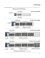
Страница 9: ...high speed networking Throughout this manual these switches will be referred to as the V1410 8 Switch V1410 16 Switch V1410 24 Switch and the V1410 24 2G Switch The V1410 8 Switch has 8 auto sensing 10 100Base TX RJ 45 ports The V1410 16 Switch has 16 auto sensing 10 100Base TX RJ 45 ports The V1410 24 Switch has 24 auto sensing 10 100Base TX RJ 45 ports HP V1410 8 Switch J9661A HP V1410 16 Switch...

Страница 10: ... ports and two 10 100 1000Base T RJ 45 ports ports 25 and 26 These switches can be directly connected to computers printers and servers toprovide dedicated bandwidthto those devices and youcanbuild a switched network infrastructure by connecting the switch to hubs other switches or routers ...

Страница 11: ...Switch J9662A Power LED Link Activity LEDs 10 100Base TX RJ 45 ports1 Speed LEDs HP V1410 24 Switch J9663A Power LED Link Activity LEDs 10 100Base TX RJ 45 ports1 Speed LEDs 1 All RJ 45 ports have the Auto MDIX feature HP V1410 24 2G Switch J9664A Power LED Link Activity LEDs 10 100Base TX RJ 45 ports1 Speed LEDs 10 100 1000Base T RJ 45 ports1 ...

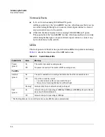
Страница 12: ...oring Table 1 1 details the functions of the LED indicators Table 1 1 Switch Status LEDs Switch LEDs State Meaning Power green On The switch is properly receiving power Off No power connection The switch is NOT receiving power Port LEDs Link Act green On The port is enabled and receiving a link indication from the connected device Off One of these condition exists no active network cable is connec...

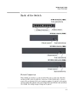
Страница 13: ...es 12 volts DC to the switch and automatically adjusts to any AC voltage between 100 240 volts and either 50 or 60 Hz No voltage range settings are required DC power connector HP V1410 8 Switch J9661A HP V1410 16 Switch J9662A HP V1410 24 Switch J9663A Power cord retention ring DC power connector Power cord retention ring 10 100Base TX RJ 45 ports DC power connector HP V1410 24 2G Switch J9664A DC...

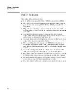
Страница 14: ...h they will also work Automatically negotiated full duplex operation for the RJ 45 ports when connected to other auto negotiating devices The 16 and 24 port models support new IEEE 802 3az features in the 100 Mbps mode This new Energy Efficient Ethernet EEE standard reduces power consumption when connected with EEE compliant client devices Automatic learning of the hardware addresses in each switc...

Страница 15: ...License and Hardware Warranty information Kit number 5066 0621 Contains three 3 4 20 mm M4 screws for wall and under table mounting three wall anchors cable tie for power cord V1410 16 Switch V1410 24 Switch V1410 24 2G Switch Kit number 5066 0622 Contains two mounting brackets eight 8 mm M4 screws to attach the mounting brackets to the switch four 5 8 inch number 12 24 screws to attach the switch...

Страница 16: ...ntinental Europe Denmark Switzerland Israel Vietnam Indonesia India Japan South Africa Taiwan Thailand United Kingdom Hong Kong Singapore Malaysia United States Canada Mexico Brazil Argentina Chile 8121 0870 8120 8373 8120 6314 8121 0702 8120 6316 8120 6317 8121 0963 8121 0664 8120 8699 8120 6313 8121 1081 8120 8367 8121 0514 Wall Plug in External AC DC Power Adapter AC Power cords are not used Un...

Страница 17: ...y agency that defines the regulations for power cords in your country The mark is your assurance that the power cord can be used safely with the switch If the supplied power cord does not fit contact HP networking support When installing the switch the AC outlet should be near the switch and should be easily accessible in case the switch must be powered off Ensure the switch does not overload the ...

Страница 18: ... into a power source and observe that the LEDs on the switch s front panel indicate correct switch operation 3 Mount the switch page 2 8 The V1410 16 V1410 24 and V1410 24 2G Switches can be mounted in a 19 inch telco rack in an equipment cabinet on a wall under a table or on a horizontal surface The switches can also be mounted on a wall under a table or on a horizontal surface 4 Connect power to...

Страница 19: ...for more information Installation Location Before installing the switch plan its location and orientation relative to other devices and equipment In the front or back of the switch depending on where the ports are located leave at least 7 6 cm 3 inches of space for the twisted pair cabling In the back of the switch leave at least 3 8 cm 1 1 2 inches of space for the power cord On the sides of the ...

Страница 20: ... of the switch and then plug the AC DC power adapter into a nearby properly grounded electrical outlet N ot e The switches are shipped with one of two types of AC DC power adapter either the universal AC DC adapter with an AC power cord or the wall plug in AC DC adapter without an AC power cord Figure 2 1 Connecting the switch power adapter Connect the wall plug in AC DC power adapter to the switc...

Страница 21: ...ower cord displaying the mark of the safety agency that defines the regulations for power cords in your country The mark is your assurance that the power cord can be used safely with the switch If the supplied power cord does not fit contact HP networking support Ca ut ion Use only the AC DC power adapter and power cord if applicable supplied with the switch Use of other adapters or power cords in...

Страница 22: ...y to be mounted in a stable location The switch can be mounted in these ways on a horizontal surface on a wall under a table rack or cabinet V1410 16 Switch V1410 24 Switch and V1410 24 2G Switch only Rack or Cabinet Mounting The V1410 16 Switch V1410 24 Switch and V1410 24 2G Switch can be rack mounted using the included brackets Note that the mounting brackets have multiple mounting holes and ca...

Страница 23: ...cket kit not included 1 Use a 1 Phillips cross head screwdriver and attach the mounting brackets to the switch with the included 8 mm M4 screws Figure 2 3 Attaching mounting brackets to the V1410 16 Switch Figure 2 4 Attaching mounting brackets to the V1410 24 and V1410 24 2G Switch 8 mm M4 screws 8 mm M4 screws ...

Страница 24: ...ck or mounting it in a more balanced position WA R NI NG For safe reliable installation only use the screws provided in the accessory kit to attach the mounting brackets to the switch 2 Hold the switch with attached brackets up to the rack and move it vertically until rack holes line up with the bracket holes then insert and tighten the four number 12 24 screws holding the brackets to the rack Fig...

Страница 25: ...2 11 Installing the Switch Installation Procedures Figure 2 6 Mounting the V1410 24 and V1410 24 2G Switch in a rack Install 12 24 screws ...

Страница 26: ... only to a wall or wood surface that is at least 1 2 inch 12 7 mm plywood or its equivalent 1 In the required location mark the position for the mounting screws For the V1410 8 Switch the hole to hole distance is 3 54 inch 90 0 mm For the V1410 16 Switch V1410 24 Switch and V1410 24 2G Switch the hole to hole distance is 5 91 inch 150 0 mm 2 Use a 1 Phillips cross head screwdriver and two of the i...

Страница 27: ...it that can be used to help keep the switch from sliding on the surface Attach the rubber feet to the four corners on the bottom of the switch within the embossed angled lines Use a sturdy surface in an uncluttered area You may want to secure the networking cables and switch power cord to the table leg or other part of the surface structure to help prevent tripping over the cords Ca ut ion Ensure ...

Страница 28: ...cable not included to attach the switch to an immovable object Figure 2 9 Using a security cable with the switch 4 Connect the Switch to a Power Source 1 Plug the AC DC adapter s power cord into the switch and then plug the AC DC power adapter into a nearby AC power source Figure 2 10 Connecting power to the switch 2 Re check the LEDs during self test See LED Behavior on page 2 8 ...

Страница 29: ...2 15 Installing the Switch Installation Procedures 3 Use the included cable tie to secure the power cord to the switch Figure 2 11 Securing the power cord cable tie ...

Страница 30: ...fortheconnecteddevice the Link Act LED for the port should lighttoconfirmapowered ondevice for example an end node is at the other end of the cable If the Link Act LED does not go on when the network cable is connected to the port see Diagnosing with the LEDs in chapter 4 Troubleshooting To disconnect Press the small tab on the plug and pull the plug out of the port RJ 45 connector Unshielded twis...

Страница 31: ...nd nodes printers and other peripherals and servers are directly connected as shown in the above illustration The end node devices are connected to the switch by straight through or crossover twisted pair cables Either cable type can be used because of the Auto MDIX feature on the switches V1410 24 2G Switch Twisted pair straight through or crossover cables Server with Gigabit Ethernet NIC Categor...

Страница 32: ...Switch and V1410 24 2G Switch with PCs printers and local servers attached are both connected to a E2510 24G Switch The devices attached to the two switches can now communicate with eachother throughthe E2510 24GSwitch They can also allcommunicate with the server that is connected to a 100Base TX port on the V1410 24 2G Switch Server E2510 24G Switch Twisted pair straight through or crossover cabl...

Страница 33: ...ugh category 5 straight through or crossover twisted pair cable Category 3 or 4 cable can also be used if the connection is 10 Mbps only The V1410 24 2G Switch and the E2510 24G Switch are connected through a 1000Base T Category 5e twisted pair cable uplink All the devices on this network segment can access other network resources that are connected elsewhere on the network ...

Страница 34: ...2 20 Installing the Switch Sample Network Topologies ...

Страница 35: ... ways to determine the link speed and the communication mode half duplex or full duplex If the connected device is also configured to Auto the switch will automatically negotiate both link speed and communication mode If the connected device has a fixed configuration for example 100 Mbps at half or full duplex the switch will automatically sense the link speed but will default to a communication m...

Страница 36: ... tester is a recommended tool for every 100Base TX and 1000Base T network installation Improper Network Topologies It is important to make sure you have a valid network topology Common topology faults include excessive cablelengthandexcessive repeaterdelaysbetweenendnodes Ifyouhave network problems after recent changes to the network change back to the previous topology If you no longer experience...

Страница 37: ...ng LED patterns for General Switch Troubleshooting 1 Check in the table for the LED pattern you see on your switch 2 Refer to the corresponding diagnostic tip on the next few pages Table 3 1 LED Error Indicators LED Pattern Indicating Problems Diagnostic Tips Power Port Link Act LED Off with power cord plugged in 1 On Off with cable connected 1 This LED is not important for the diagnosis ...

Страница 38: ...ted properly Verify the connected device and switch are both powered on and operating correctly Verify you have used the correct cable type for the connection For twisted pair connections to the fixed 10 100 1000 ports either straight through orcrossover cables can be used because of the switch s Auto MDIX feature and the Auto MDI MDI X feature of the 10 100 1000 T port For1000Base Tconnections ve...

Страница 39: ...Type 10Base T 100Base TX or 1000Base T standards The twisted pair cables attached to the switch must be compatible with the appropriate standards To verify your cable is compatible with these standards use a qualified cable test device Testing End to End Network Communications Both the switch and the cabling can be tested by running an end to end communications test a test that sends known data fr...

Страница 40: ...ormation Additionally your HP authorized network reseller can provide you with assistance both with services that they offer and with services offered by HP Before Calling Support Before calling your networking dealer or HP Support to make the support process most efficient you first should retrieve the following information Information Item Information Location product identification the front of...

Страница 41: ... 2 cm 4 4 in 4 4 cm 1 73 in 0 82 kg 1 8 lbs V1410 24 2G Switch J9664A 33 6 cm 13 23 in 16 9 cm 6 65 in 4 4 cm 1 73 in 1 35 kg 2 98 lbs AC voltage Maximum current Frequency range Universal inline power adapter 5066 1122 100 240 volts 0 5A 50 60 Hz Wall plug in power adapter 5184 5863 or 5184 5864 100 240 volts 0 4A 50 60 Hz DC voltage DC Maximum current V1410 8 Switch J9661A 12 volts 0 3A V1410 16 ...

Страница 42: ... 2 No 60950 1 UL 60950 1 Operating Non Operating Temperature 0 C to 40 C 32 F to 104 F 40 C to 70 C 40 F to 158 F Relative humidity non condensing 15 to 95 at 40 C 104 F 15 to 90 at 65 C 149 F Maximum altitude 3048 m 10 000 ft 3048 m 10 000 ft Switch Model Combined BTU V1410 8 Switch 12 28 BTU hr 12 96 KJ hr V1410 16 Switch 12 28 BTU hr 12 96 KJ hr V1410 24 Switch 16 38 BTU hr 17 28 KJ hr V1410 24...

Страница 43: ...nuation Near End Crosstalk NEXT and Far End Crosstalk FEXT Additionally unlike the cables for 100BASE TX the 1000BASE T cables must pass tests for Equal Level Far End Crosstalk ELFEXT and Return Loss When testing your cabling be sure to include the patch cables that connect the switch and other end devices to the patch panels on your site The patch cables are frequently overlooked when testing cab...

Страница 44: ...cables or crossover cables If you happen to use a correctly wired crossover cable though the switch will still be able to automatically detect the MDI MDI X operation and link correctly to the connected device N ot e Using Fixed Configurations If the port configuration is changed to any of the fixed configurations though for example 100 Mbps full duplex the port operates as MDI X only and the corr...

Страница 45: ... Connector Pin Outs For 100 Mbps connections to the ports use 100 ohm Category 5 UTP or STP cable only as supported by the IEEE 802 3u Type 100Base TX standard For 1000 Mbps connections 100 ohm Category 5e or better cabling is recommended ...

Страница 46: ...s Full Duplex the ports operate as MDI X ports and straight through cables must be then used for connections to PC NICs and other MDI ports Cable Diagram N ot e Pins 1 and 2 on connector A must be wired as a twisted pair to pins 1 and 2 on connector B Pins 3 and 6 on connector A must be wired as a twisted pair to pins 3 and 6 on connector B Pins 4 5 7 and 8 are not used in this application althoug...

Страница 47: ...ports operate as MDI X ports and crossover cables must be then used for connections to hubs or switches or other MDI X network devices Cable Diagram N ot e Pins 1 and 2 on connector A must be wired as a twisted pair to pins 3 and 6 on connector B Pins 3 and 6 on connector A must be wired as a twisted pair to pins 1 and 2 on connector B Pins 4 5 7 and 8 are not used in this application although the...

Страница 48: ...tor A must be wired as a twisted pair to pins 1 and 2 on connector B Pins 3 and 6 on connector A must be wired as a twisted pair to pins 3 and 6 on connector B Pins 4 and 5 on connector A must be wired as a twisted pair to pins 4 and 5 on connector B Pins 7 and 8 on connector A must be wired as a twisted pair to pins 7 and 8 on connector B Pin Assignments For 1000Base T operation all four pairs of...

Страница 49: ...cial environment This equipment gener ates uses and can radiate radio frequency energy and if not installed and used in accordance with the instruction manual may cause interference to radio communications Operation of this equipment in a residential area may cause interference in which case the user will be required to correct the interference at his own expense Canada This product complies with ...

Страница 50: ...B 2 EMC Regulatory Statements Regulatory Statements Japan VCCI Class A Korea Taiwan ...

Страница 51: ...VXEMHFW WR WKH IROORZLQJ WZR FRQGLWLRQV WKLV GHYLFH PD QRW FDXVH KDUPIXO LQWHUIHUHQFH DQG WKLV GHYLFH PXVW DFFHSW DQ LQWHUIHUHQFH UHFHLYHG LQFOXGLQJ LQWHUIHUHQFH WKDW PD FDXVH XQGHVLUHG RSHUDWLRQ 7KH SURGXFW KHUHZLWK FRPSOLHV ZLWK WKH UHTXLUHPHQWV RI WKH RZ 9ROWDJH LUHFWLYH WKH 0 LUHFWLYH DQG FDUULHV WKH PDUNLQJ DFFRUGLQJO Additional Information 7KLV SURGXFW LV DVVLJQHG D 5HJXODWRU 0RGHO 1XPEHU ZK...

Страница 52: ...R WKH IROORZLQJ WZR FRQGLWLRQV WKLV GHYLFH PD QRW FDXVH KDUPIXO LQWHUIHUHQFH DQG WKLV GHYLFH PXVW DFFHSW DQ LQWHUIHUHQFH UHFHLYHG LQFOXGLQJ LQWHUIHUHQFH WKDW PD FDXVH XQGHVLUHG RSHUDWLRQ 7KH SURGXFW KHUHZLWK FRPSOLHV ZLWK WKH UHTXLUHPHQWV RI WKH RZ 9ROWDJH LUHFWLYH WKH 0 LUHFWLYH DQG FDUULHV WKH PDUNLQJ DFFRUGLQJO Additional Information 7KLV SURGXFW LV DVVLJQHG D 5HJXODWRU 0RGHO 1XPEHU ZKLFK VWD V...

Страница 53: ...R WKH IROORZLQJ WZR FRQGLWLRQV WKLV GHYLFH PD QRW FDXVH KDUPIXO LQWHUIHUHQFH DQG WKLV GHYLFH PXVW DFFHSW DQ LQWHUIHUHQFH UHFHLYHG LQFOXGLQJ LQWHUIHUHQFH WKDW PD FDXVH XQGHVLUHG RSHUDWLRQ 7KH SURGXFW KHUHZLWK FRPSOLHV ZLWK WKH UHTXLUHPHQWV RI WKH RZ 9ROWDJH LUHFWLYH WKH 0 LUHFWLYH DQG FDUULHV WKH PDUNLQJ DFFRUGLQJO Additional Information 7KLV SURGXFW LV DVVLJQHG D 5HJXODWRU 0RGHO 1XPEHU ZKLFK VWD V...

Страница 54: ... WR WKH IROORZLQJ WZR FRQGLWLRQV WKLV GHYLFH PD QRW FDXVH KDUPIXO LQWHUIHUHQFH DQG WKLV GHYLFH PXVW DFFHSW DQ LQWHUIHUHQFH UHFHLYHG LQFOXGLQJ LQWHUIHUHQFH WKDW PD FDXVH XQGHVLUHG RSHUDWLRQ 7KH SURGXFW KHUHZLWK FRPSOLHV ZLWK WKH UHTXLUHPHQWV RI WKH RZ 9ROWDJH LUHFWLYH WKH 0 LUHFWLYH DQG FDUULHV WKH PDUNLQJ DFFRUGLQJO Additional Information 7KLV SURGXFW LV DVVLJQHG D 5HJXODWRU 0RGHO 1XPEHU ZKLFK VWD...

Страница 55: ...on A 7 cables twisted pair HP Auto MDIX feature A 4 wiring rules A 4 cables twisted pair connector pin outs A 4 cabling infrastructure 2 5 Clear button location on switch 1 3 connecting the switch to a power source 2 14 console port location on switch 1 3 cross over cable pin out A 7 D description back of switch 1 5 front of switch 1 3 LEDs 1 4 switch 1 1 desktop switch sample topology 2 17 diagno...

Страница 56: ...al surface 2 13 on a wall 2 12 precautions 2 12 N network cables HP Auto MDIX feature A 4 required types 2 5 twisted pair connector pin outs A 4 twisted pair wiring rules A 4 network devices connecting to the switch 2 16 network ports connecting to 2 16 location on switch 1 4 types of 1 4 non standard network cables effects 3 2 P parts included with the switch 2 1 physical specifications switch A ...

Страница 57: ...ifications A 1 switch operation verifying after installation 2 6 T testing diagnostic tests 3 5 end to end communications 3 5 switch operation 3 5 twisted pair cabling 3 5 tips for troubleshooting 3 1 topologies effects of improper topology 3 2 samples of 2 17 troubleshooting 3 1 basic tips 3 1 common network problems 3 1 connecting to fixed full duplex devices 3 1 diagnostic tests 3 5 effects of ...

Страница 58: ...4 Index ...

Страница 59: ...herein is subject to change without notice The only warranties for HP products and services are set forth in the express warranty statements accompanying such products and services Nothing herein should be construed as constituting an additional warranty HP will not be liable for technical or editorial errors or omissions contained herein April 2011 Manual Part Number 5998 0946 ...

Отзывы: