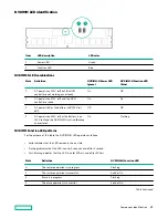
Smart Carrier NVMe (SCN) drive LED definitions
The NVMe drive is a PCIe bus device. A device attached to a PCIe bus cannot be removed without allowing the device and
bus to complete and cease the signal/traffic flow.
CAUTION: Do not remove an NVMe drive from the drive bay while the Do not remove LED is flashing. The Do not
remove LED flashes to indicate that the device is still in use. Removing the NVMe drive before the device has
completed and ceased signal/traffic flow can cause loss of data.
Item
LED
Status
Definition
1
Locate
Solid blue
The drive is being identified by a host application.
Flashing blue
The drive carrier firmware is being updated or requires an update.
2
Activity
ring
Rotating green
Drive activity
Off
No drive activity
3
Drive
status
Solid green
The drive is a member of one or more logical drives.
Flashing green
The drive is doing one of the following:
• Rebuilding
• Performing a RAID migration
• Performing a stripe size migration
• Performing a capacity expansion
• Performing a logical drive extension
• Erasing
Flashing amber/
green
The drive is a member of one or more logical drives and predicts the drive will fail.
Flashing amber
The drive is not configured and predicts the drive will fail.
Solid amber
The drive has failed.
Off
The drive is not configured by a RAID controller.
4
Do not
remove
Solid white
Do not remove the drive. The drive must be ejected from the PCIe bus prior to
removal.
Table Continued
Component identification
28
Содержание HPE ProLiant DX360 Gen10
Страница 7: ...Regulatory information 183 Documentation feedback 184 Acronyms and abbreviations 185 7 ...
Страница 44: ...Operations 44 ...
Страница 74: ...8 Route and connect the data cable 9 Route and connect the power cable Hardware options installation 74 ...
Страница 101: ... Full length Hardware options installation 101 ...
Страница 107: ... 10 SFF SAS SATA NVMe Combo 4 LFF Hardware options installation 107 ...
Страница 125: ...8 Using a Torx T 10 screwdriver remove the Power UID USB assembly 8 SFF 4 LFF Hardware options installation 125 ...
Страница 129: ...6 Install the 4 LFF display port USB module 7 Route and connect the cable Hardware options installation 129 ...
Страница 150: ...2 SFF backplane to P816i a controller 10 SFF NVMe backplane to NVMe riser Cabling 150 ...
Страница 151: ...2 SFF NVMe backplane to primary riser 1 SFF rear backplane to system board SATA Cabling 151 ...


