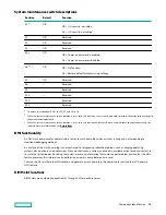
Description
Status
Over temp LED
Off = Normal
Amber = High system temperature detected
Amp Status LED
Off = AMP modes disabled
Solid green = AMP mode enabled
Solid amber = Failover
Flashing amber = Invalid configuration
Power cap LED
Off = System is in standby, or no cap is set.
Solid green = Power cap applied
For Networking Choice (NC) server models, the embedded NIC ports are not equipped on the server. Therefore, the NIC LEDs on the
Systems Insight Display will flash based on the FlexibleLOM network port activity. In the case of a dual-port FlexibleLOM, only NIC LED
1 and 2 will illuminate to correspond with the activity of the respective network ports.
When the health LED on the front panel illuminates either amber or red, the server is experiencing a health event. For
more information on the combination of these LEDs, see
Systems Insight Display combined LED descriptions).
Systems Insight Display combined LED descriptions
The combined illumination of the following LEDs indicates a system condition:
• Systems Insight Display LEDs
• System power LED
• Health LED
Systems Insight Display LED
and color
Health LED System power
LED
Status
Processor (amber)
Red
Amber
One or more of the following conditions
might exist:
• Processor in socket X has failed.
• Processor X is not installed in the
socket.
• Processor X is unsupported.
• ROM detects a failed processor during
POST.
Processor (amber)
Amber
Green
Processor in socket X is in a pre-failure
condition.
DIMM (amber)
Red
Green
One or more DIMMs have failed.
Table Continued
Component identification
14
Содержание HPE ProLiant DX360 Gen10
Страница 7: ...Regulatory information 183 Documentation feedback 184 Acronyms and abbreviations 185 7 ...
Страница 44: ...Operations 44 ...
Страница 74: ...8 Route and connect the data cable 9 Route and connect the power cable Hardware options installation 74 ...
Страница 101: ... Full length Hardware options installation 101 ...
Страница 107: ... 10 SFF SAS SATA NVMe Combo 4 LFF Hardware options installation 107 ...
Страница 125: ...8 Using a Torx T 10 screwdriver remove the Power UID USB assembly 8 SFF 4 LFF Hardware options installation 125 ...
Страница 129: ...6 Install the 4 LFF display port USB module 7 Route and connect the cable Hardware options installation 129 ...
Страница 150: ...2 SFF backplane to P816i a controller 10 SFF NVMe backplane to NVMe riser Cabling 150 ...
Страница 151: ...2 SFF NVMe backplane to primary riser 1 SFF rear backplane to system board SATA Cabling 151 ...


