background image


Before you begin  5 


WARNING:

  To reduce the risk of personal injury from high-leakage current, verify earth 

connection before connecting the power supply.   

The summation of input power for multiple pieces of information technology equipment through 

the use of power products can result in high-leakage currents. 

If the total system leakage current for a system of components exceeds 3.5 mA: 

  The use of a detachable input power cord is prohibited. 

  The input power cord must be securely attached, and it should be connected to the AC 

mains by hardwiring or through the use of a non-residential, industrial-style plug that 

maintains positive earth connection. 

  If the total system leakage current through the ground conductor exceeds 5% of the input 

current per line under normal operating conditions, the system loads should be divided 

among multiple power connections. 


Required tools 

The following tools are required for installation: 


Phillips screwdriver 


Torx screwdriver 


Additional requirements 

If your facility or configuration requires an L5-20R plug, you must obtain a third-party L5-20R to NEMA 

5-20P adapter before installing or connecting the H5M54A 1.9kVA 120V Basic PDU. 

Содержание H5M54A

Страница 1: ...s for the person who installs and maintains HPE PDU products Hewlett Packard Enterprise assumes you are qualified in the installation of electrical equipment and trained in recognizing hazards in products with hazardous energy levels Part Number 720595 003a April 2016 Edition 6 ...

Страница 2: ...ly warranties for Hewlett Packard Enterprise products and services are set forth in the express warranty statements accompanying such products and services Nothing herein should be construed as constituting an additional warranty Hewlett Packard Enterprise shall not be liable for technical or editorial errors or omissions contained herein ...

Страница 3: ... 4 Important safety information 4 Required tools 5 Additional requirements 5 Recommended hardware configurations 6 Configurations 6 Hardware installation 9 Installing the PDU 9 Installing 1U and 0U PDUs 13 Securing the cables 17 Acronyms and abbreviations 18 Documentation feedback 19 ...

Страница 4: ...ock and hazardous energy levels exists The installation of options and routine maintenance and service of this product must be performed by individuals who are knowledgeable about the procedures precautions and hazards associated with AC power products Follow these safety precautions when connecting multiple hardware components to power sources WARNING To reduce the risk of fire electric shock and...

Страница 5: ...ached and it should be connected to the AC mains by hardwiring or through the use of a non residential industrial style plug that maintains positive earth connection If the total system leakage current through the ground conductor exceeds 5 of the input current per line under normal operating conditions the system loads should be divided among multiple power connections Required tools The followin...

Страница 6: ...d hardware configurations Configurations The PDU is installed in a rack in the following configurations A single PDU configuration with the outlets facing the center of the rack A single PDU configuration with the outlets facing the rear of the rack ...

Страница 7: ...Recommended hardware configurations 7 A double PDU configuration with the outlets facing the center of the rack An inverted PDU with the input power cable exiting the top of the rack ...

Страница 8: ...Recommended hardware configurations 8 1U and 0U configurations ...

Страница 9: ...front of the rack or on the opposite side of the rack from the following images install the components on the opposite side of the PDU shown in the images 1 Align and install the power cord retention bracket with the screw holes marked C 2 Align and install the mounting pins with the screw holes marked M ...

Страница 10: ...Hardware installation 10 3 If installing the PDU inverted install a mounting pin on the bottom of the PDU 4 If needed install the input power cable retention band ...

Страница 11: ...11 5 If needed insert and secure the power cable 6 Install the PDU and ensure the mounting pins are engaged with the rack CAUTION When moving a rack with installed components always use the shipping bracket to secure the PDU ...

Страница 12: ...dware installation 12 7 If the PDU is not inverted install the shipping bracket above the PDU 8 If the PDU is installed above 39U flip the PDU shipping bracket to allow space for the rack shipping bracket ...

Страница 13: ...erted install the shipping bracket over the mounting pin below the PDU Installing 1U and 0U PDUs 1 Attach the power cord retention bracket 2 Attach the appropriate mounting brackets Each bracket only requires two screws per side for this product ...

Страница 14: ...Hardware installation 14 o 1U bracket installation o 0U bracket installation 3 Install cage nuts 4 Install the PDU ...

Страница 15: ...Hardware installation 15 o 1U installation ...

Страница 16: ...Hardware installation 16 o 0U installation ...

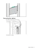
Страница 17: ...Hardware installation 17 Securing the cables Secure the cable weight to the retention bracket The installation is complete ...

Страница 18: ...Acronyms and abbreviations 18 Acronyms and abbreviations AC alternating current ITE Information Technology Equipment kVA kilovolt ampere PDU power distribution unit PFC power factor corrected ...

Страница 19: ...tion send any errors suggestions or comments to Documentation Feedback mailto docsfeedback hpe com When submitting your feedback include the document title part number edition and publication date located on the front cover of the document For online help content include the product name product version help edition and publication date located on the legal notices page ...

Отзывы: