483
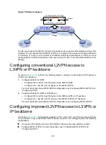
Figure 130 Network diagram
The PE-agg connects the MPLS L2VPN and the backbone through the L2VE interface and the L3VE
interface. You can assume that the MPLS L2VPN is connected to the backbone through an Ethernet
or VLAN link. If a user is not connected to the MPLS L2VPN through Ethernet or VLAN, you must
configure MPLS L2VPN interworking on the user access PE (PE 1) and the L2VE interface of the
PE-agg.
Configuring conventional L2VPN access to
L3VPN or IP backbone
As shown in
, perform the following tasks to configure conventional L2VPN access to
L3VPN or IP backbone:
1.
Configure the MPLS L2VPN:
{
Configure PE 1 and PE 2 as PE devices in the MPLS L2VPN.
{
Configure CE 1 and PE 3 as CE devices in the MPLS L2VPN.
For more information about MPLS L2VPN configuration, see "Configuring MPLS L2VPN" and
"Configuring VPLS."
2.
Configure the MPLS L3VPN or IP backbone:
{
Configure PE 3 and PE 4 as PE devices in the MPLS L3VPN or IP backbone.
{
Configure CE 1 and CE 2 as CE devices in the MPLS L3VPN or IP backbone.
For more information about MPLS L3VPN configuration, see "Configuring MPLS L3VPN."
Configuring improved L2VPN access to L3VPN or
IP backbone
As shown in
, configurations required on PE 1, PE 4, CE 1, and CE 2 are similar to those
on the devices in the conventional L2VPN access scenario. The PE-agg requires the following
configurations:
•
Create an L2VE interface and an L3VE interface that have the same interface number.
•
Configure MPLS L2VPN. For more information, see "Configuring MPLS L2VPN" and
"Configuring VPLS."
CE 2
MPLS L3VPN/
IP backbone
PE 4
MPLS L2VPN
access network
PE 1
PE-agg
CE 1
VPN 1
Site 1
VPN 1
Site 2
VE-L2VPN
VE-L3VPN
Packet processing in PE-agg
Input interface
Output interface


