background image


Rear components 

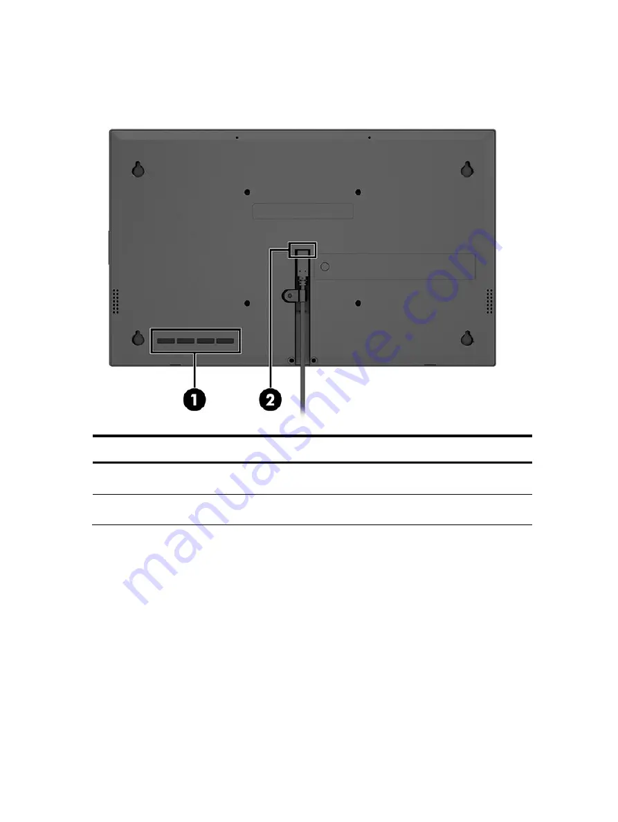
To identify the components on the rear of the monitor, use this illustration and table. 


Table 1-2: Rear components and their descriptions 

Component 

Function 

(1)


OSD control buttons 

Open the OSD menu and make adjustments to 

monitor settings. 

(2)


USB Type-C connector 

Connects USB Type-C cable to provide signal 

and power to the monitor. 


Содержание Engage 14

Страница 1: ...Maintenance and Service Guide Engage 14 14t model SUMMARY This guide provides information about spare parts removal and replacement of parts diagnostic tests problem troubleshooting and more ...

Страница 2: ...ates and other countries The information contained herein is subject to change without notice The only warranties for HP products and services are set forth in the express warranty statements accompanying such products and services Nothing herein should be construed as constituting an additional warranty HP shall not be liable for technical or editorial errors or omissions contained herein First E...

Страница 3: ...urning the repaired product to the customer 3 2 Monitor features 4 Features 4 Front components 5 Rear components 6 Locating the serial number and product number 7 3 Illustrated parts catalog 9 How to order parts 10 4 Removal and replacement procedures 11 Preparation for disassembly 11 Rear Cover 12 Connector repair 15 Type C Connector repair J6 16 Function test 17 Support and troubleshooting 18 In...

Страница 4: ......

Страница 5: ...mer or make the product unsafe Use proper safety devices to ensure your personal safety Always use approved tools and test equipment for servicing Never assume the product s power is disconnected from the main power supply Check that it is disconnected before opening the product s cabinet Modules containing electrical components are sensitive to electrostatic discharge ESD Follow ESD safety proced...

Страница 6: ...ement 1 A professional repairer must have the technical competence to repair electronic displays and comply with the applicable regulations for repairers of electrical equipment in the Member States where the repairer operates Reference to an official registration system as professional repairer where such a system exists in the Member States shall be accepted as proof of compliance 2 A profession...

Страница 7: ... no firmware is posted the monitor does not need a firmware update Before returning the repaired product to the customer Perform an AC leakage current check on exposed metallic parts to be sure the product is safe to operate without the potential of electrical shock Do not use a line isolation transformer during this check Measurements that are not within specified limits present a possible shock ...

Страница 8: ...e to meet requirements for reduced power consumption Wide viewing angle to allow viewing from a sitting or standing position or moving from side to side Four on screen display OSD buttons three that you can reconfigure to quickly allow selection of the most commonly used operations On screen display OSD adjustments in several languages for easy setup and screen optimization Energy saver feature to...

Страница 9: ...nitor use this illustration and table Table 1 1 Front components and their descriptions Component Description 1 Webcam light On The camera is in use 2 Webcam Transmits your image in a video conference 3 Microphones Record sound 4 Power button Turns the monitor on or off ...

Страница 10: ... use this illustration and table Table 1 2 Rear components and their descriptions Component Function 1 OSD control buttons Open the OSD menu and make adjustments to monitor settings 2 USB Type C connector Connects USB Type C cable to provide signal and power to the monitor ...

Страница 11: ...the serial number and product number The serial number and product number are located on labels on the rear of the monitor You might need these numbers when contacting HP for support Spec label Engage14 Engage14t ...

Страница 12: ...8 Barcode label Engage14 Engage14t ...

Страница 13: ...omponents use this illustration and table Item Description Qty 1 TOUCH 1 2 BEZEL 1 3 PANEL 1 4 MAIN FRAME 1 5 TANSFER BD 1 6 MAIN BD MYLAR 1 7 MAIN BD 1 8 MAIN BD BRACKET 2 9 STAND 1 10 COVER BENTO 1 11 CABLE TYPE C 1 12 PLATE TYPE C 1 13 SPEAKER 2 14 CASE REAR 1 ...

Страница 14: ...C J6 Call HP Service Call HP Service NOTE The connector may need to be modified to meet functionality regulatory and safety requirements if it is not an exact match You can purchase cables from the HP part store at https partsurfer hp com Search aspx NOTE HP continually improves and changes product parts For complete and current information about supported parts for your computer go to http partsu...

Страница 15: ...ce information and precautions sections in the Getting started chapter of this guide 2 Clean the room for disassembly 3 Identify the disassembly area 4 Check the position that the monitors are to be placed along with the number of monitors Prepare the area for material flow according to the disassembly layout 5 Be sure to have the following equipment and materials Press fixture Working table Screw...

Страница 16: ...12 Rear Cover S1 Release screws on monitor then separate the stand from monitor head S2 Release screws label type C cable ...

Страница 17: ...13 S3 Then remove cover rear tape FFC PCBA S4 Remove screw bracket FFC wire PCBA Speaker ...

Страница 18: ...14 S5 Take off MAIN BD MAIN BD ...

Страница 19: ... A connectors The connectors are on the main board board part number 5E 4QW01 00 The connectors identifiers are as follows Connector Location Type C J6 Before repairing connectors follow these steps Prepare the monitor for disassembly See Preparation for disassembly on page 11 ...

Страница 20: ...dering iron and absorber You can gently push down with the soldering iron once everything is molten to move the connector out of the through holes 2 Lift connector from the PCB 3 Place new component on the location and must check it can match PCB footprint 4 Soldering the new component by solder iron ...

Страница 21: ...ction test After repair be sure to confirm that all functions are working Table 4 1 Function test Test item Operating description Tool used Type C Check the Type C device whether works normally Type C device ...

Страница 22: ...sources Image appears blurred indistinct or too dark Brightness setting is too low Open the OSD menu and select Brightness to adjust the brightness scale as needed Check Video Cable is displayed on the screen Monitor video cable is disconnected Connect the appropriate video signal cable between the computer and monitor Be sure that the computer power is off while connecting the video cable Input S...

Страница 23: ...ustrated parts catalog 9 P parts 9 parts ordering 11 precautions 2 preparation for disassembly 12 R rear components 6 removal and replacement procedures 12 returning to customer 3 RoHS 2002 95 EC requirements 2 S safety information 1 serial number location 7 service information 2 spare parts 9 support and troubleshooting 19 T troubleshooting 19 Type C 6 ...

Отзывы: