background image

Positioning the computer

This computer may ship with a recline stand or an adjustable height stand.

Adjusting a recline stand

Adjusting an adjustable height stand

Adjusting a recline stand

CAUTION:

Use caution when reclining a computer if a cable lock is installed. The cable or the lock may interfere 

with the rotation or the angle of recline.

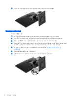
This stand allows you to position the computer from a reclining position to an upright position.
To adjust the computer position from the reclining position to an upright position:

1.

Grasp both top and bottom of the computer and lift the computer to the highest point.

2.

Press the bottom of the computer down and adjust to the appropriate tilt.

To adjust the computer position from an upright position to the reclining position:

1.

Lift the bottom of the computer until it is level with the top.

14

Chapter 2   Setup

Содержание EliteOne 800 G3

Страница 1: ...Hardware Reference Guide HP EliteOne 800 G3 23 inch All in One Business PC ...

Страница 2: ...ess warranty statements accompanying such products and services Nothing herein should be construed as constituting an additional warranty HP shall not be liable for technical or editorial errors or omissions contained herein This document contains proprietary information that is protected by copyright No part of this document may be photocopied reproduced or translated to another language without ...

Страница 3: ...s manner indicates that failure to follow directions could result in bodily harm or loss of life CAUTION Text set off in this manner indicates that failure to follow directions could result in damage to equipment or loss of information NOTE Text set off in this manner provides important supplemental information iii ...

Страница 4: ...iv About This Book ...

Страница 5: ...ing and removing an adjustable height stand 9 Attaching an adjustable height stand 9 Removing an adjustable height stand 9 Attaching the computer to a mounting fixture 10 Connecting and disconnecting cables 11 Connecting cables 11 Connecting a display 11 Disconnecting cables 12 Removing and installing the rear port cover 12 Removing the rear port cover 12 Installing the rear port cover 13 Position...

Страница 6: ...y 27 Memory module specifications 27 Populating memory module slots 27 Installing memory modules 28 Replacing the RTC Battery 29 Replacing drives 30 Replacing a hard drive 30 Removing a hard drive 30 Installing a 2 5 inch hard disk drive 31 Replacing the optical disc drive 32 Appendix A Electrostatic discharge 35 Preventing electrostatic damage 35 Grounding methods 35 Appendix B Computer operating...

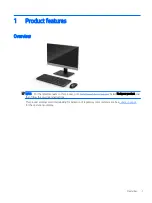
Страница 7: ... this product go to http www hp com support Select Find your product and then follow the on screen instructions This product employs electronic labeling for indication of regulatory mark or statement See Labels on page 6 for the operation to display Overview 1 ...

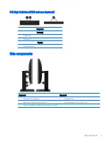
Страница 8: ...onents Infrared IR webcam optional Component Component Front View 1 Webcam light 4 IR webcam 2 IR light 5 Rear webcam adjustment wheel 3 Full High Definition FHD webcam Top view 6 Digital microphones Rear view 7 Webcam light 8 FHD webcam 2 Chapter 1 Product features ...

Страница 9: ...2 FHD webcam Top view 3 Digital microphones Side components Component Component 1 Optical disc drive optional 4 Headphone jack 2 Optical disc drive eject button optional 5 Fingerprint reader Touch models only 3 Audio out headphone Audio in microphone combo jack Side components 3 ...

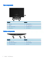
Страница 10: ...ts 2 3 USB 3 1 Type A ports 2 7 Stereo audio out jack 4 Power connector 8 Security cable slot Bottom components Component Component 1 USB 3 1 Type A port 4 USB 3 1 Type C port 2 USB 3 1 Type A charging port 5 Hard drive activity light 3 SD card reader optional 6 Power button 4 Chapter 1 Product features ...

Страница 11: ... features Your keyboard and mouse may be different Component Component 1 Sleep 6 Mute Volume 2 Fast Reverse 7 Decrease Volume 3 Play Pause 8 Increase Volume 4 Stop 9 Function 5 Fast Forward Keyboard features 5 ...

Страница 12: ...nstalled with Windows 8 or Windows 8 1 do not have the physical label but have a Digital Product Key electronically installed NOTE This Digital Product Key is automatically recognized and activated by Microsoft Operating Systems on a reinstall of the Windows 8 or Windows 8 1 operating system with HP approved recovery methods 2 Service label Provides important information to identify your computer ...

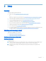
Страница 13: ... a security cable on page 18 Turn on the power See Connecting power on page 18 The mouse and keyboard are synchronized at the factory Should you ever need to synchronize the mouse and keyboard again see Synchronizing the optional wireless keyboard and mouse on page 20 Attaching and removing a stand Two stands are available for the computer Attaching and removing a recline stand Attaching and remov...

Страница 14: ...connect the AC power cord from the AC outlet and disconnect any external devices 4 Place the computer face down on a soft flat surface HP recommends that you set down a blanket towel or other soft cloth to protect the bezel and screen surface from scratches or other damage 5 Remove the rear port cover if it is installed For instructions see Removing the rear port cover on page 12 6 Press the relea...

Страница 15: ...move the stand 1 Remove all removable media such as optical discs or USB flash drives from the computer 2 Turn off the computer properly through the operating system then turn off any external devices 3 Disconnect the AC power cord from the AC outlet and disconnect any external devices 4 Place the computer face down on a soft flat surface HP recommends that you set down a blanket towel or other so...

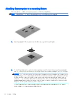
Страница 16: ...puter supports the VESA industry standard 100 mm mounting holes To attach a third party mounting solution to the computer four 4 mm 0 7 pitch and 20 mm long screws are required These screws are supplied with the computer Longer screws must not be used because they may damage the computer It is important to verify that the manufacturer s mounting solution is compliant with the VESA standard and is ...

Страница 17: ...y The DisplayPort and HDMI connectors on the rear of the computer allow you to connect displays to the computer If your computer has Intel graphics you may connect up to two displays in one of the following configurations Two displays daisy chained to the DisplayPort One display connected to the DisplayPort and one to the HDMI port If your computer has AMD graphics you may connect up to four displ...

Страница 18: ...r Then connect a cable VGA or DVI depending on your application between the adapter and a display 5 Replace the rear port cover on the computer 6 Turn on power to the computer and the display NOTE Use the graphics card software or the Windows Display Settings to configure the display as a mirrored image of the computer display or an extension of the computer display Disconnecting cables 1 You may ...

Страница 19: ...s in the top of the rear port compartment 3 Slide the port cover 1 in until the tabs click into place 4 Slide the rear port cover retainer tabs away from each other 2 to lock the port cover in place 5 You may prevent access to internal components and ports by securing the rear port cover Use a T15 tamper resistant Torx screwdriver to screw the two security lock screws into the chassis 3 Removing a...

Страница 20: ... angle of recline This stand allows you to position the computer from a reclining position to an upright position To adjust the computer position from the reclining position to an upright position 1 Grasp both top and bottom of the computer and lift the computer to the highest point 2 Press the bottom of the computer down and adjust to the appropriate tilt To adjust the computer position from an u...

Страница 21: ...ecline This stand allows you to Tilt the computer from 5 to 20 from the desktop Adjust the computer height within a range of 110 mm 4 3 in Rotate the computer from the landscape to portrait view Swivel the computer up to 45 to either side To tilt the computer grasp the top and bottom of the computer and adjust to the appropriate tilt To change the height of the computer grasp both sides of the com...

Страница 22: ...he computer orientation between landscape and portrait be sure that the HP logo on the front of the computer is either on the bottom or the left side To change from landscape to portrait view 1 Lift the computer to the highest position to provide clearance 2 Grasp the upper right and lower left corners of the computer and lift the lower left corner until the computer is in the portrait position To...

Страница 23: ...s of the computer and lift the lower right corner until the computer is in the landscape position To swivel the computer from side to side Grasp both sides of the computer and swivel it up to 45 to one side or the other Positioning the computer 17 ...

Страница 24: ...y cable slot on the computer Secure the security cable lock with the key CAUTION Use caution when adjusting the tilt swivel or height of the computer if a security cable is installed The cable or the lock may interfere with the adjustment Connecting and disconnecting power Connecting power 1 Plug the power cord into a AC outlet 2 Press the power button on the side of the computer to turn it on 18 ...

Страница 25: ...ream online video conferences Send and receive Instant messages Schedule meetings Maintain security over conversations Webcam operation To release the webcam press it down to unlock it To close the webcam press it down until it locks Setting up Windows Hello If the Windows 10 operating system is installed on your computer follow these steps to set up Windows Hello facial recognition 1 Select the S...

Страница 26: ...nd mouse are optional components The mouse and keyboard are synchronized at the factory If they do not work remove and replace the batteries If the mouse and keyboard are still not synchronized then follow this procedure to manually re synchronize the pair 1 2 20 Chapter 2 Setup ...

Страница 27: ...nd keyboard still do not work then remove and replace the batteries If the mouse and keyboard are still not synchronized then synchronize the keyboard and mouse again Synchronizing the optional wireless keyboard and mouse 21 ...

Страница 28: ...om the AC outlet grasp the cord by the plug To reduce the risk of serious injury read the Safety Comfort Guide It describes proper workstation setup and provides guidelines for posture and work habits that increase your comfort and decrease your risk of injury It also provides electrical and mechanical safety information This guide is located on the web at http www hp com ergo CAUTION Static elect...

Страница 29: ...wireless keyboard remove the battery door on the underside of the keyboard 1 and lift the batteries out of the battery compartment 2 To remove batteries from the wireless mouse remove the battery door on the underside of the mouse 1 and lift the batteries out of the battery compartment 2 Removing batteries from the optional wireless keyboard or mouse 23 ...

Страница 30: ...to the memory modules as long as the computer is plugged into an active AC outlet Adding or removing memory modules while voltage is present may cause irreparable damage to the memory modules or system board 4 Remove disengage any security devices that prohibit opening the computer 5 Place the computer face down on a soft flat surface HP recommends that you set down a blanket towel or other soft c...

Страница 31: ...nd removing a stand on page 7 3 Reconnect all cables to the computer See Connecting cables on page 11 4 Reinstall the rear port cover See Installing the rear port cover on page 13 5 Relock any security devices that were disengaged when the access panel was removed 6 Place the computer in the upright position 7 Plug the power cord into a AC outlet Removing and replacing the computer access panel 25...

Страница 32: ...Locating internal components Component Component 1 Memory modules 3 Optical disc drive optional 2 RTC battery 4 Hard drive 26 Chapter 3 Hardware repair and upgrade ...

Страница 33: ... for this computer and advises that the consumer purchase it to avoid compatibility issues with unsupported third party memory Populating memory module slots The system will automatically operate in single channel mode dual channel mode or flex mode depending on how the memory modules are installed Refer to the following table to identify the memory module channel locations Location System board l...

Страница 34: ...e Locating internal components on page 26 3 To remove a memory module press outward on the two latches on each side of the memory module 1 then pull the memory module out of the slot 2 4 Slide the new memory module into the slot at approximately a 30 angle 1 then press the memory module down 2 so that the latches lock it in place NOTE A memory module can be installed in only one way Match the notc...

Страница 35: ...ment Before beginning these procedures ensure that you are discharged of static electricity by briefly touching a grounded metal object NOTE The lifetime of the lithium battery can be extended by plugging the computer into a live AC outlet The lithium battery is only used when the computer is NOT connected to AC power HP encourages customers to recycle used electronic hardware HP original print ca...

Страница 36: ...e optical disc drive ODD To locate the hard drive on the system board see Locating internal components on page 26 Removing a hard drive 1 Remove the access panel For instructions see Removing the computer access panel on page 24 2 Pull the hard drive latch away from the hard drive to release the drive 1 3 Slide the hard drive toward the edge of the computer and lift the hard drive out of the drive...

Страница 37: ...replacement drive For instructions on installing a hard drive see Installing a 2 5 inch hard disk drive on page 31 Installing a 2 5 inch hard disk drive 1 Fasten four mounting screws with grommets onto the new 2 5 inch hard drive 2 Position the hard drive above the drive cage with the connectors facing the center of the computer Replacing drives 31 ...

Страница 38: ...ions see Replacing the computer access panel on page 25 Replacing the optical disc drive The optical disc drive is located under the hard drive on the right side of the computer To locate the optical disc drive on the system board see Locating internal components on page 26 1 Remove the access panel For instructions see Removing the computer access panel on page 24 2 Remove the hard drive For inst...

Страница 39: ...t of the chassis 4 Pull the green latch off the optical disc drive Keep this latch to install on the new optical disc drive 5 Align the three pins on the latch with the holes in the new optical disc drive and press the latch firmly onto the new drive NOTE You must reuse the latch removed from the old optical disc drive Replacing drives 33 ...

Страница 40: ... it snaps into place NOTE The optical disc drive can be installed in only one way 7 Replace the hard drive For instructions see Installing a 2 5 inch hard disk drive on page 31 8 Replace the access panel For instructions see Replacing the computer access panel on page 25 34 Chapter 3 Hardware repair and upgrade ...

Страница 41: ...ng methods Use one or more of the following methods when handling or installing electrostatic sensitive parts Use a wrist strap connected by a ground cord to a grounded workstation or computer chassis Wrist straps are flexible straps with a minimum of 1 megohm 10 percent resistance in the ground cords To provide proper ground wear the strap snug against the skin Use heelstraps toestraps or bootstr...

Страница 42: ...e enclosure and the same operating guidelines listed above will still apply Keep liquids away from the computer and keyboard Never cover the ventilation slots with any type of material Install or enable power management functions of the operating system or other software including sleep states Turn off the computer before you do any of the following Wipe the exterior of the computer with a soft da...

Страница 43: ...ked by an authorized HP service provider Shipping preparation Follow these suggestions when preparing to ship the computer 1 Back up the hard drive files to an external storage device Be sure that the backup media is not exposed to electrical or magnetic impulses while stored or in transit NOTE The hard drive locks automatically when the system power is turned off 2 Remove and store all removable ...

Страница 44: ... For additional information about a particular assistive technology product contact customer support for that product Contacting support We are constantly refining the accessibility of our products and services and welcome feedback from users If you have an issue with a product or would like to tell us about accessibility features that have helped you please contact us at 888 259 5707 Monday throu...

Страница 45: ...e 2 5 inch installing 31 hard drive 2 5 inch 30 2 5 inch removing 30 replacing 30 self encrypting 30 solid state 30 types 30 I installation guidelines 22 installing 2 5 inch hard disk drive 31 battery 29 display 11 memory 28 optical disc drive 32 internal components 26 IR webcam components 2 K keyboard features 5 removing batteries 23 synchronizing wireless 20 L labels Certificate of Authenticity ...

Страница 46: ...p order of 7 shipping preparation 37 side components 3 SODIMM identification 27 location 27 specifications 27 specifications memory 27 stands adjustable height attaching 9 adjustable height removing 9 attaching and removing 7 positioning 14 recline attaching 7 recline removing 8 synchronizing wireless keyboard and mouse 20 T top components 2 V ventilation guidelines 36 VESA mounting holes 10 W war...

Отзывы: