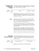
Channel Current
Gain Calibration
Registers
The Channel Current Gain Calibration Registers store current gain
calibration constants in non-volatile memory. There are 16 registers,
one for each output channel. The register at base + 160
16
stores channel 1,
base + 162
16
stores channel 2, up to base 17E
16
to store channel 16. This
register is non-volatile.
Address
Base + 160
16
through
Base + 17E
16
Bit
15
14
13
12
11
10
09
08
07
06
05
04
03
02
01
00
msb
lsb
WRITE
Unused
Current Gain Calibration Constant
Current Gain Calibration Constant: Writing a 16-bit value to this field
sets a new constant used to calibrate the channel output. Values are in the
range:
000
16
minimum gain
800
16
nominal gain
FFF
16
maximum gain
Notes
Registers 00100
16
through 001BE
16
are located in non-volatile (FLASH)
memory. Writing to this memory requires a complicated sequence of
register accesses not documented here. It is recommended that calibration
be performed using the SCPI driver for the module, not register access.
Non-volatile memory has finite life, based upon the number of writes.
Use care when writing to this memory.
The contents of this register are loaded into volatile memory at power-on
and not used on an on-going basis.
147 HP E1418A Register-Based Programming
Appendix B
Содержание E1418A
Страница 6: ...Notes 6 Contents HP E1418A 8 16 Channel D A Converter Module ...
Страница 10: ...Notes 10 HP E1418A User s Manual ...
Страница 12: ...12 HP E1418A User s Manual ...
Страница 105: ...TRIGger 105 HP E1418A SCPI Command Reference Chapter 3 ...
Страница 111: ...Notes HP E1418A Command Quick Reference 111 HP E1418A SCPI Command Reference Chapter 3 ...
Страница 135: ...135 HP E1418A Register Based Programming Appendix B ...
Страница 157: ...Notes 156 HP E1418A Error Messages Appendix C ...
Страница 164: ...Figure D 4 Resistance Calibration Connections CAL Appendix D Voltage Current Output Adjustment 163 ...
Страница 170: ...Notes Appendix D Voltage Current Output Adjustment 169 ...
Страница 174: ...Figure E 1 8 Channel Disassembly 172 Configuration and Disassembly Appendix E ...
Страница 175: ...Figure E 2 16 Channel Disassembly Appendix E Configuration and Disassembly 173 ...
Страница 177: ...Figure E 3 Plug on Channel Locations Figure E 4 Installing Plug on Modules Appendix E Configuration and Disassembly 175 ...
Страница 192: ...Notes 192 HP E1418A 8 16 Channel D A Converter Module Index ...


