MF877-00 Page 2
Template Revision C, 30-July-2018
Copyright 2018 Hewlett Packard Enterprise Development LP
HPE instructions for this template are available at
Item Description
Notes
Quantity
of items
included
in
product
Cathode Ray Tubes (CRT)
0
Capacitors / condensers (Containing PCB/PCT)
0
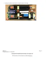
Electrolytic Capacitors / Condensers measuring
greater than 2.5 cm in diameter or height
Count varies depending on PSU model
2 or 9
External electrical cables and cords
1 power cord for each of 2 power supplies.
4 SAS expansion cables for each of 2 IOMs.
2 RJ45 cable for each of 2 IOMs.
14 max
Gas Discharge Lamps
0
Plastics containing Brominated Flame
Retardants weighing > 25 grams (not including
PCBs or PCAs already listed as a separate item
above)
0
Components and parts containing toner and ink,
including liquids, semi-liquids (gel/paste) and
toner
Include the cartridges, print heads, tubes, vent
chambers, and service stations.
0
Components and waste containing asbestos
0
Components, parts and materials containing
refractory ceramic fibers
0
Components, parts and materials containing
radioactive substances
0
2.0 Tools Required
List the type and size of the tools that would typically be used to disassemble the product to a point where
components and materials requiring selective treatment can be removed.
Tool Description
Tool Size (if
applicable)
Phillips driver
#0, #1, #2
Torx driver
T10, T15
Pliers
Small
Drill
Standard
3.0 Product Disassembly Process
3.1 List the basic steps that should typically be followed to remove components and materials requiring selective
treatment:
1. Remove the top drive bay cover.
2. Remove the bezel and hubcaps from the front of the enclosure.
3. Remove all disk drives.
4. For each disk drive, remove the disk from the plastic carrier.
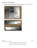
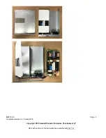
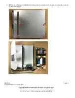
5. Remove both power cooling modules (PCMs).
6. Remove both IOMs.
7. Remove each rear fan module.
8. Remove both controller fans.
9. Disassemble each PCM. See the PCM disassembly procedure.


