HP COMPAQ NC4200 Скачать руководство пользователя страница 94

Removal and Replacement Procedures

Maintenance and Service Guide

6–5

6.3 Preparing the Notebook for 

Disassembly

Before you begin any removal or installation procedures: 

1. Shut down the notebook. If you are unsure whether the 

notebook is off or in hibernation, turn the computer on, 
and then shut it down through the operating system.

2. Disconnect all external devices connected to the notebook.

3. Disconnect the power cord.

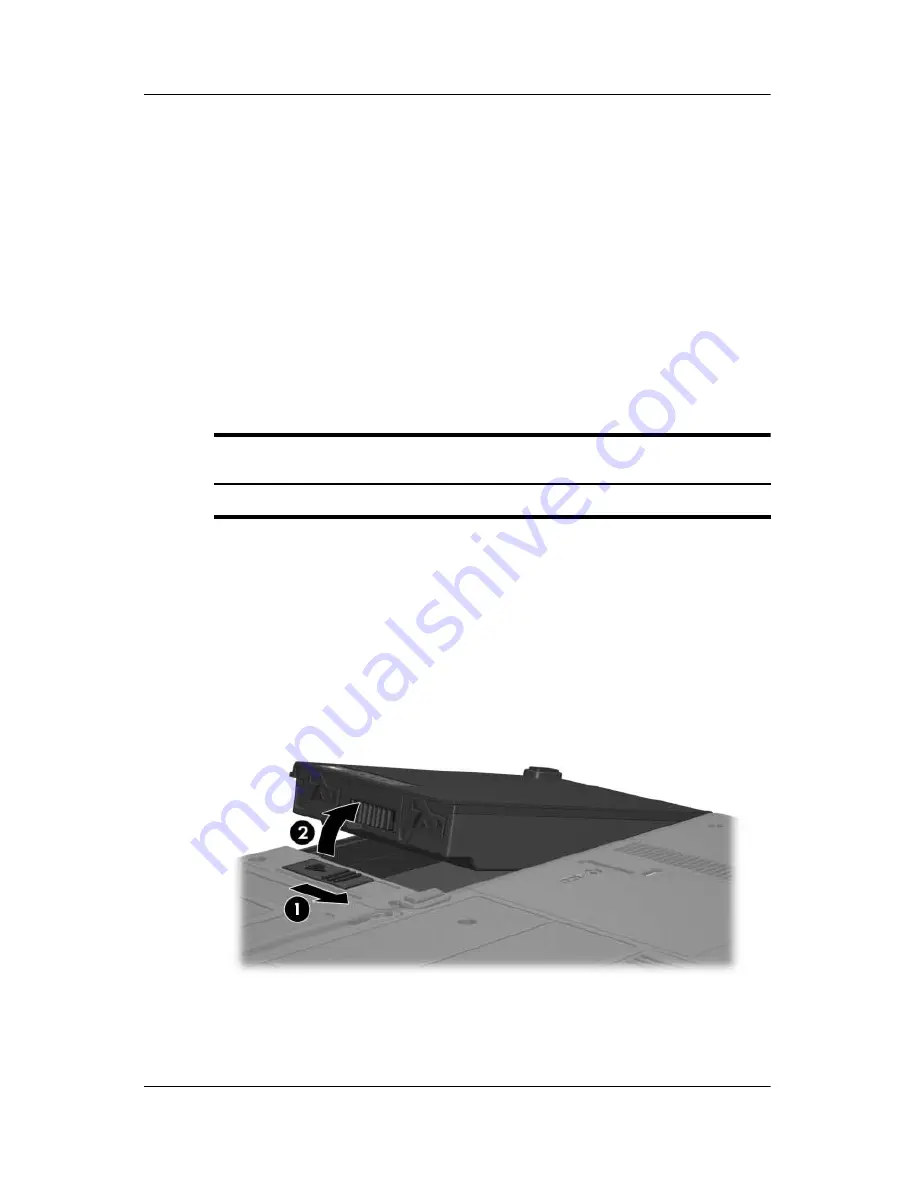
4. Remove the battery pack by following these steps:

a. Turn the notebook upside down with the rear panel 

toward you.

b. Slide the battery release latch 

1

 toward you. (The left side 

of the battery pack disengages from the notebook.)

c. Lift the left side of the battery pack and swing it to the 

right 

2

 to remove it.

Removing the Battery Pack

Reverse the above procedure to install the battery pack.

Battery Pack Spare Part Number Information

6-cell battery pack

383510-001

Содержание COMPAQ NC4200

Страница 1: ...24 002 April 2007 This guide is a troubleshooting reference used for maintaining and servicing the notebook It provides comprehensive information on identifying notebook features components and spare parts troubleshooting notebook problems and performing notebook disassembly procedures ...

Страница 2: ...ny under license SD Logo is a trademark of its proprietor The information contained herein is subject to change without notice The only warranties for HP products and services are set forth in the express warranty statements accompanying such products and services Nothing herein should be construed as constituting an additional warranty HP shall not be liable for technical or editorial errors or o...

Страница 3: ... allow another hard surface such as an adjoining optional printer or a soft surface such as pillows or rugs or clothing to block airflow Also do not allow the AC adapter to contact the skin or a soft surface such as pillows or rugs or clothing during operation The computer and the AC adapter complies with the user accessible surface temperature limits defined by the International Standard for Safe...

Страница 4: ...t 1 5 1 4 External Components 1 6 1 5 Design Overview 1 20 2 Troubleshooting 2 1 Computer Setup 2 1 Accessing Computer Setup 2 2 Computer Setup Defaults 2 2 Selecting from the File Menu 2 3 Selecting from the Security Menu 2 4 Selecting from the Tools Menu 2 5 Selecting from the Advanced Menu 2 6 2 2 Troubleshooting Flowcharts 2 7 ...

Страница 5: ...cs Hardware Kit 4 10 4 4 Miscellaneous Cable Kit 4 11 4 5 Miscellaneous Not Illustrated 4 12 4 6 Sequential Part Number Listing 4 14 5 Removal and Replacement Preliminaries 5 1 Tools Required 5 1 5 2 Service Considerations 5 2 Plastic Parts 5 2 Cables and Connectors 5 2 5 3 Preventing Damage to Removable Drives 5 3 5 4 Preventing Electrostatic Damage 5 4 5 5 Packaging and Transporting Precautions ...

Страница 6: ... Module 6 10 6 7 External Memory Module 6 12 6 8 TPM Security Card 6 15 6 9 Keyboard Cover 6 16 6 10 Keyboard 6 18 6 11 Fan 6 22 6 12 Heat Sink 6 23 6 13 Processor 6 26 6 14 Internal Memory Module 6 28 6 15 Mini PCI Communications Card 6 30 6 16 Display Assembly 6 32 6 17 Button Board 6 38 6 18 Top Cover 6 42 6 19 TouchPad 6 46 6 20 Speaker 6 50 6 21 Infrared Board 6 52 6 22 System Board 6 54 6 23...

Страница 7: ...viii Maintenance and Service Guide Contents 7 Specifications A Connector Pin Assignments B Power Cord Set Requirements C Screw Listing Index ...

Страница 8: ...nce and Service Guide 1 1 1 Product Description The HP Compaq nc4200 Notebook PC offers advanced modularity Intel Pentium M and Celeron M processors and extensive multimedia support HP Compaq nc4200 Notebook PC ...

Страница 9: ... 2 0 GB Microsoft Windows XP Home Edition or Windows XP Professional varying by notebook model Full size Windows keyboard with embedded numeric keypad TouchPad and pointing stick pointing devices including a dedicated vertical scroll region Integrated 10Base T 100Base T 1000Base T Ethernet local area network LAN network interface card NIC with RJ 45 jack Integrated high speed 56K modem with RJ 11 ...

Страница 10: ...y pack varying by notebook model Audio speaker Volume up volume mute and volume down buttons Connectors Infrared Audio out headphone Audio in microphone Universal Serial Bus USB v 2 0 3 ports 1 powered Power External monitor RJ 45 network RJ 11 modem S Video out PC Card SD Card Primary battery Travel battery Docking connector ...

Страница 11: ... to Section 4 3 Miscellaneous Plastics Hardware Kit for more information 2 Remove the real time clock RTC battery refer to Section 6 24 RTC Battery for more information on removing and replacing the RTC battery 3 Wait approximately 5 minutes 4 Replace the RTC battery and reassemble the notebook 5 Connect AC power to the notebook Do not reinsert any battery packs at this time 6 Turn on the notebook...

Страница 12: ...tend battery operating time and conserve power The notebook supports the following power management features Standby Hibernation Setting customization by the user Hotkeys for setting the level of performance Battery calibration Lid switch standby resume Power standby button Advanced Configuration and Power Management ACPM compliance ...

Страница 13: ... are shown below and described in Table 1 1 Front Components Table 1 1 Front Components Item Component Function 1 Wireless light On One or more optional internal wireless devices such as a WLAN device and or Bluetooth device are turned on 2 Power standby light Green The notebook is on Blinking green The notebook is in standby mode ...

Страница 14: ...rnal power source the light is turned off when all batteries in the notebook are fully charged If the notebook is not connected to an external power source the light is turned off until the battery reaches a low battery condition when the light begins blinking amber 4 Integrated Drive Electronics IDE drive light On A drive in the hard drive bay is being accessed 5 Fast IrDA select models only Link...

Страница 15: ...1 8 Maintenance and Service Guide Product Description The external components on the right side of the notebook are shown below and described in Table 1 2 Right Side Components ...

Страница 16: ...single sound channel or stereo dual sound channel microphone 3 Powered USB port Connects USB 1 1 or 2 0 compliant devices to the notebook using a standard USB cable or connects an optional external MultiBay or external MultiBay II to the notebook This USB port is a powered port that can be used without external power 4 PC Card slot eject button Ejects PC Cards from the PC Card slot 5 PC Card slot ...

Страница 17: ...ent Function 1 Security cable slot Attaches an optional security cable to the notebook The purpose of security solutions is to act as deterrents These deterrents may not prevent a product from being mishandled or stolen 2 Vent Enables airflow to cool internal components Ä To prevent overheating do not obstruct vents Using the notebook on a soft surface such as a pillow blanket rug or thick clothin...

Страница 18: ... used software solutions 6 Power switch When the notebook is Off slide toward the front of the notebook and release to turn on the notebook In standby slide toward the front of the notebook and release to exit standby In hibernation slide toward the front of the notebook and release to exit hibernation If the notebook has stopped responding and Microsoft Windows shutdown procedures cannot be used ...

Страница 19: ...1 12 Maintenance and Service Guide Product Description The external components on the rear panel of the notebook are shown below and described in Table 1 4 Rear Panel Components ...

Страница 20: ...ble Enabled with 10 100 1000BaseT connectivity 4 Power connector Connects an AC adapter an optional AC adapter or an optional power cable 5 External monitor port Connects an optional VGA external monitor or projector 6 S Video out jack Is a 7 pin dual purpose jack It connects an optional S Video device such as a television VCR camcorder overhead projector or video capture card with an optional sta...

Страница 21: ...1 14 Maintenance and Service Guide Product Description The standard keyboard components of the notebook are shown below and described in Table 1 5 Standard Keyboard Components ...

Страница 22: ...ck and turns on the caps lock light 3 fn key Executes frequently used system functions when pressed in combination with a function key or the esc key 4 Windows logo key Displays the Microsoft Windows Start menu 5 Windows applications key Displays a shortcut menu for items beneath the pointer 6 Arrow keys Moves the cursor around the screen 7 Embedded numeric keypad Can be used like an external nume...

Страница 23: ...1 16 Maintenance and Service Guide Product Description The notebook top components are shown below and described in Table 1 6 Top Components ...

Страница 24: ...uch as scrolling selecting and double clicking 3 Left and right pointing stick buttons 2 Function like the left and right buttons on an external mouse 4 Pointing stick Moves the pointer 5 Vent Enables airflow to cool internal components 6 Presentation Mode button Turns on Presentation mode 7 Volume mute button Mutes or restores volume 8 Volume down button Decreases notebook sound 9 Volume up butto...

Страница 25: ...1 18 Maintenance and Service Guide Product Description The external components on the bottom of the notebook are shown below and described in Table 1 7 Bottom Components ...

Страница 26: ...to an optional docking device 3 Travel battery connector Connects an optional travel battery 4 Vents 3 Enable airflow to cool internal components 5 Primary battery bay Holds the primary battery pack 6 Primary battery release latch Releases the primary battery pack from the battery bay 7 Hard drive cover Holds the primary hard drive 8 Expansion memory module compartment Contains one expansion memor...

Страница 27: ... devices PC Card Pointing stick TouchPad Trusted platform module TPM security module ÄCAUTION To properly ventilate the notebook allow at least a 7 6 cm 3 inch clearance on the left and right sides of the notebook The notebook uses an electric fan for ventilation The fan is controlled by a temperature sensor and is designed to be turned on automatically when high temperature conditions exist These...

Страница 28: ... repairs can create a safety hazard Any indication of component replacement or printed wiring board modification may void any warranty or exchange allowances 2 1 Computer Setup Computer Setup is a preinstalled ROM based utility that can be used even when the operating system is not working or will not load If the operating system is working the notebook restarts the operating system after you exit...

Страница 29: ...hanges use the arrow keys to select File Ignore changes and exit and then follow the instructions on the screen To exit and save all the settings you have entered use the arrow keys to select File Save changes and exit and then follow the instructions on the screen Your preferences are set when you exit Computer Setup and take effect when the notebook restarts Computer Setup Defaults To return all...

Страница 30: ...specification information about the processor memory and cache size video revision keyboard controller version and system ROM Save to floppy Save system configuration settings to a diskette Restore from floppy Restore system configuration settings from a diskette Restore defaults Replace configuration settings in Computer Setup with factory default settings Identification information is retained I...

Страница 31: ... when you enter Computer Setup by turning on not restarting the notebook Smart Card Security Enable disable power on support for smart cards This feature is supported by select smart card readers only Embedded Security Enable Disable the embedded security chip Restore embedded security chip to factory settings Enable Disable power on authentication support Enable Disable automatic DriveLock Reset ...

Страница 32: ... To Do This HDD Self Test options Run a quick or comprehensive self test on any hard drive in the system Battery Information View information about any battery packs in the notebook Memory Check Run a self test on memory modules in the notebook View information about memory modules installed in the notebook ...

Страница 33: ...ly a single usually nonstandard pointing device at startup select Disable Enable Disable USB legacy support for a USB keyboard mouse and hub When USB legacy support is enabled A USB keyboard mouse and hub work even when a Windows operating system is not loaded The notebook starts from a bootable hard drive diskette drive diskette or CD CD RW or DVD inserted into a drive connected by a USB connecto...

Страница 34: ...rt 2 2 4 Flowchart 2 4 No Power Part 3 2 5 Flowchart 2 5 No Power Part 4 2 6 Flowchart 2 6 No Video Part 1 2 7 Flowchart 2 7 No Video Part 2 2 8 Flowchart 2 8 Nonfunctioning Docking Device if applicable 2 9 Flowchart 2 9 No Operating System OS Loading 2 10 Flowchart 2 10 No OS Loading Hard Drive Part 1 2 11 Flowchart 2 11 No OS Loading Hard Drive Part 2 2 12 Flowchart 2 12 No OS Loading Hard Drive...

Страница 35: ...rive 2 15 Flowchart 2 15 No Audio Part 1 2 16 Flowchart 2 16 No Audio Part 2 2 17 Flowchart 2 17 Nonfunctioning Device 2 18 Flowchart 2 18 Nonfunctioning Keyboard 2 19 Flowchart 2 19 Nonfunctioning Pointing Device 2 20 Flowchart 2 20 No Network Modem Connection Table 2 5 Troubleshooting Flowcharts Overview Continued ...

Страница 36: ...g device work ing Go to Flowchart 2 17 Nonfunc tioning Device Go to Flowchart 2 2 No Power Part 1 Go to Flowchart 2 6 No Video Part 1 All drives working Y Y Y Y Y Y Y Y N N N N N End N N N Go to Flowchart 2 9 NoOperating System OS Loading Go to Flowchart 2 15 No Audio Part 1 Go to Flowchart 2 18 Nonfunc tioning Keyboard or Flowchart 2 19 Nonfunc tioning Pointing Device Check LED board speaker conn...

Страница 37: ... up on AC power Power up in docking device Power up on battery power Power up in docking device Done Reset power Reset power Power up on AC power N Y Y N N Y N N Y Y Y N 1 On select models there is a separate reset button 2 On select models the notebook can be reset using the standby switch and either the lid switch or the main power switch NOTES Go to Flowchart 2 4 No Power Part 3 Go to Flowchart...

Страница 38: ...Flowchart 2 2 No Power Part 1 Visually check for debris in battery socket and clean if necessary Done N Y Power on Check battery by recharging it moving it to another notebook or replacing it Power on Done Y Replace power supply if applicable N Power on Done Y N Go to Flowchart 2 4 No Power Part 3 ...

Страница 39: ...seat AC adapter in notebook and at power source Internal or external AC adapter Done Done Done Done Power on Power on Power on Plug directly into AC outlet Power LED on Power outlet active Try different outlet Replace external AC adapter Replace power cord Y N Y Y Y Y N N N N External Internal Go to Flowchart 2 5 No Power Part 4 ...

Страница 40: ...boards and replace damaged items Open notebook Loose or damaged parts Y Close notebook and retest Power on Done N Replace the following items if applicable Check notebook operation after each replacement 1 Internal DC DC converter 2 Internal AC adapter 3 Processor board 4 System board NOTE Replace these items as a set to prevent shorting out among components ...

Страница 41: ...ay 3 System board Internal or external display Adjust brightness Video OK Done Docking Device Internal Stand alone External Adjust brightness Video OK Done Y Press lid switch to ensure operation Video OK Done Y N Video OK Done Done N Check for bent pins on cable Try another display Internal and external video OK Replace system board Y Y N N NOTE To change from internal to external display use the ...

Страница 42: ...ess Video OK Video OK Done Done Check that notebook is properly seated in docking device for bent pins on cable and for monitor connection Go to A in Flowchart 2 6 No Video Part 1 Check brightness of external monitor Try another external monitor Internal and external video OK Go to Flowchart 2 8 Nonfunction ing Docking Device if applica Y Y Y N N N Remove notebook from dock ing device if connected...

Страница 43: ...king device and power outlet N Check voltage setting on docking device Reset monitor cable connector at docking device Reinstall notebook into dock ing device Docking device operating Docking device operating Done Done Y Nonfunctioning docking device Remove notebook replace docking device Test replacement docking device with new notebook ...

Страница 44: ...ocking device and power outlet No OS loading NOTE Before beginning troubleshooting always check cable connections cable ends and drives for bent or damaged pins No OS loading from diskette drive go to Flowchart 2 13 No OS Loading Dis kette Drive No OS loading from optical drive go to Flowchart 2 14 No OS Loading Optical Drive No OS loading from network go to Flowchart 2 20 No Network Modem Connect...

Страница 45: ...drive Nonsystem disk message Go to Flowchart 2 11 No OS Load ing Hard Drive Part 2 Reseat external hard drive OS loading Done Boot from CD Go to Flowchart 2 13 No OS Loading Dis kette Drive Boot from hard drive Boot from diskette Change boot priority through the Setup utility and reboot Boot from hard drive Y Y Y Y Y N N N N N Check the Setup utility for correct booting order ...

Страница 46: ...to Flowchart 2 13 No OS Loading Dis kette Drive Format hard drive and bring to a bootable C prompt Create partition and then format hard drive to boot able C prompt Boot from diskette drive Remove disc or diskette and reboot Y N Boot from hard drive Y N Y N Hard drive accessible Y N Hard drive accessible Done Run FDISK Y N Hard drive partitioned Hard drive formatted Y N Y N Notebook booted Done Y ...

Страница 47: ... ing Hard Drive Part 2 Clean virus Done N Install OS and reboot Virus on hard drive OS loading from hard drive Y N Y N Y N Diagnostics on disc or diskette Replace hard drive Run diagnostics and follow recommendations Run SCANDISK and check for bad sectors Can bad sectors be fixed Replace hard drive Y N Y N Fix bad sectors Boot from hard drive Replace hard drive Done ...

Страница 48: ...sk message Bootable diskette in drive Install bootable diskette and reboot notebook Check diskette for system files Try different diskette Nonsystem disk error OS loading Boot from another device Enable drive and cold boot notebook Is diskette drive boot order cor rect Change boot priority using the Setup utility Go to Flowchart 2 17 Nonfunc tioning Device Diskette drive enabled in the Setup utili...

Страница 49: ...and reboot notebook Go to Flowchart 2 17 Nonfunction ing Device Go to Flowchart 2 17 Nonfunctioning Device Install bootable disc Boots from CD or DVD Boots from CD or DVD Try another bootable disc Booting from another device Booting order correct Correct boot order using the Setup utility Done Reseat drive Y Y Y Y Y N N N N N Reset the notebook Refer to Section 1 2 Resetting the Notebook for instr...

Страница 50: ...ernally Go to Flowchart 2 16 No Audio Part 2 Go to Flowchart 2 17 Nonfunctioning Device Replace the following docking device compo nents one at a time as applicable Check audio status after each change 1 Reseat docking device audio cable 2 Replace audio cable 3 Replace speaker 4 Replace docking device audio board 5 Replace backplane board 6 Replace I O board Y Y Y Y N N N Go to Flowchart 2 16 No A...

Страница 51: ... Audio driver in OS configured Audio Y Y Y N N N Correct drivers for application Connect to external speaker Load drivers and set configuration in OS Audio Done Replace audio board and speaker connections in notebook if applicable Replace the following components individually retesting after each replacement Internal speakers Audio board if applicable ...

Страница 52: ... cables and plugs for bent or broken pins or other damage Reseat device Clear CMOS Done Fix or replace broken item Nonfunctioning device Reattach device Close notebook plug in power and reboot Device boots properly Go to Flowchart 2 9 No Operat ing System OS Loading Device boots properly Replace hard drive Replace diskette drive Replace NIC If integrated NIC replace system board Y N Y N ...

Страница 53: ...yboard operating properly Keyboard not operating prop erly External device works Replace system board Replace system board Connect notebook to good external key board Reseat internal key board connector if applicable Replace internal keyboard or cable Y N Y N Done Done Keyboard operating properly ...

Страница 54: ...t operating properly External device works Replace system board Replace system board Connect notebook to good external pointing device Reseat internal pointing device connector if applicable Replace internal pointing device or cable Y N Y N Done Done Pointing device operating properly Pointing device operating properly ...

Страница 55: ...m connec tion N Done Digital line Network or modem jack active Replace jack or have jack acti vated Connect to nondigital line NIC modem configured in OS Reload drivers and recon figure Reseat NIC modem if applicable Replace NIC modem if applicable Replace system board Done N N N N Y Y Y Y Network or modem connec tion working Network or modem connec tion working ...

Страница 56: ...urrently installed on the computer ÄCAUTION If your computer is connected to a network it is recommended that you consult with your network administrator before installing any software updates especially system BIOS updates The computer system BIOS is stored on the system ROM The BIOS initializes the operating system determines how the computer will interact with the hardware devices and provides ...

Страница 57: ...eed to know the version of the system BIOS currently installed BIOS version information also known as ROM date and System BIOS can be displayed by pressing fn esc if you are already in Microsoft Windows or by opening Computer Setup To use Computer Setup for displaying BIOS information 1 Open Computer Setup by turning on or restarting the computer and then pressing f10 while the F10 ROM Based Setup...

Страница 58: ...ontain a file named Readme txt A Readme txt file contains information regarding installing and troubleshooting the file The Readme txt files included with ROMPaqs are provided in English only Downloading a BIOS Update ÄCAUTION To prevent damage to the computer or an unsuccessful installation download and install a BIOS update only when the computer is connected to reliable external power using the...

Страница 59: ...IOS version currently installed on your computer Make a note of the date name or other identifier You may need this information to locate the update later after it has been downloaded to your hard drive b Follow the instructions on the screen to download your selection to the hard drive Make a note of the path to the location on your hard drive where the BIOS update will be downloaded You will nee...

Страница 60: ...at contains the update 3 Double click the file with an exe extension for example filename exe The BIOS installation begins 4 Complete the installation by following the instructions on the screen After a message on the screen reports a successful installation you may delete the downloaded file from your hard drive Recovering the BIOS The BIOS recovery procedure requires a USB diskette drive and a f...

Страница 61: ...he Softpaq and let the Softpaq create the ROMPaq diskette 4 Press and hold the Windows logo key B on the notebook keyboard do not use an external keyboard and turn on the notebook and wait for the caps lock light to start blinking 5 Release the Windows logo key B The BIOS recovery procedure takes approximately one minute to read the image from the diskette and then an additional 15 seconds to prog...

Страница 62: ...apter provides an illustrated parts breakdown and a reference for spare part numbers 4 1 Serial Number Location When ordering parts or requesting information provide the notebook serial number and model number located on the bottom of the notebook Serial Number Location ...

Страница 63: ...4 2 Maintenance and Service Guide Illustrated Parts Catalog 4 2 Notebook Major Components Notebook Major Components ...

Страница 64: ...nmark Europe France French Canada Germany Hungary Iceland Israel Italy Japan Korea Latin America The Netherlands Norway 383458 181 383458 201 383458 221 383458 081 383458 021 383458 051 383458 121 383458 041 383458 211 383458 DD1 383458 BB1 383458 061 383458 291 383458 AD1 383458 161 383458 331 383458 091 People sRepublic of China Poland Portugal Russia Saudi Arabia South Africa Spain Slovakia Swe...

Страница 65: ...4 4 Maintenance and Service Guide Illustrated Parts Catalog Notebook Major Components ...

Страница 66: ...16 001 9 Memory modules PC24200 1024 MB 512 MB 256 MB 383536 001 383542 001 383538 001 PC23200 1024 MB 512 MB 256 MB 383535 001 383541 001 383537 001 10 Mini PCI communications cards 802 11g Silverton wireless local access network WLAN card for use in most of the world 802 11g Silverton WLAN card for use in the rest of the world 381302 001 381303 001 802 11a b g FRLN WLAN card for use in Europe 80...

Страница 67: ...4 6 Maintenance and Service Guide Illustrated Parts Catalog Notebook Major Components ...

Страница 68: ...st of the world 337407 291 337407 001 337407 002 802 11a b g ATMC WLAN card for use in Japan 802 11a b g ATMC WLAN card for use in MOW 802 11a b g ATMC WLAN card for use in the rest of the world 377408 291 377408 001 377408 002 11 Heat sink includes thermal paste 383559 001 12 Processors include thermal paste Intel Pentium M 2 13 GHz Intel Pentium M 2 00 GHz Intel Pentium M 1 86 GHz Intel Pentium ...

Страница 69: ...4 8 Maintenance and Service Guide Illustrated Parts Catalog Notebook Major Components ...

Страница 70: ...peaker 383557 001 16 Modem board high speed 56K includes modem cable 383534 001 17 RTC battery 383625 001 18 Base enclosure cover 383520 001 19 Infrared board includes cable 383512 001 20 Base enclosure 383509 001 21 6 cell battery pack 383510 001 22 Hard drives all 5400 rpm include cover frame and connector 80 GB 80 GB 60 GB 40 GB 405839 001 383527 001 383526 001 383525 001 23 TPM security module...

Страница 71: ...arts Catalog 4 3 Miscellaneous Plastics Hardware Kit Table 4 2 Spare Part Number 383549 001 Item Description 1 Hard drive cover 2 Bluetooth cover 3 PC Card slot space saver 4 Memory module compartment cover includes 2 captive screws 5 Notebook feet 5 ...

Страница 72: ...trated Parts Catalog Maintenance and Service Guide 4 1 1 4 4 Miscellaneous Cable Kit Table 4 3 Spare Part Number 383516 001 Item Description 1 LED board cable 2 RJ 11 cable 3 TouchPad cable 4 Bluetooth cable ...

Страница 73: ...001 Docking Station Miscellaneous Plastics Kit 380045 001 Power supply 65 watt 338136 001 Keyboard point stick cap blue 404150 001 Rubber domes 383524 001 Inverter 383532 001 Microphone 383543 001 Smart card reader 411337 001 LCD center hinge cap 383518 001 Power cords For use in Belgium Europe Greece Norway and Portugal 350188 021 Brazil 350188 201 Canada French Canada Latin America Taiwan Thaila...

Страница 74: ...weden Finland 350188 B71 Screw Kit includes the following screws refer to Appendix C Screw Listing for more information on specifications and usage 383556 001 Phillips PM2 5 13 0 spring loaded screw Phillips PM3 0 4 0 screw Phillips PM2 5 7 0 screw Phillips PM2 0 5 0 screw Phillips PM2 0 4 0 screw Phillips PM1 5 3 5 screw Torx 8 M2 0 18 0 screw Torx 8 M2 0 9 0 screw Torx 8 M2 0 7 5 screw Torx 8 M2...

Страница 75: ...136 001 65 watt power supply 350188 001 Power cord for use in Canada French Canada Latin America Taiwan Thailand and the United States 350188 021 Power cord for use in Belgium Europe Greece Norway and Portugal 350188 031 Power cord for use in Hong Kong and the United Kingdom 350188 041 Power cord for use in Germany 350188 051 Power cord for use in France 350188 061 Power cord for use in Italy 3501...

Страница 76: ...02 11a b g FRLN WLAN Mini PCI communications card for use in the rest of the world 372420 001 Adjustable notebook stand 374803 001 Docking Station 374804 001 Advanced Docking Station 377408 001 802 11a b g ATMC WLAN Mini PCI communications card for use in most of the world 377408 002 802 11a b g ATMC WLAN Mini PCI communications card for use in the rest of the world 377408 291 802 11a b g ATMC WLA...

Страница 77: ...yboard with pointing stick for use in Italy 383458 071 Keyboard with pointing stick for use in Spain 383458 081 Keyboard with pointing stick for use in Denmark 383458 091 Keyboard with pointing stick for use in Norway 383458 101 Keyboard with pointing stick for use in Sweden 383458 111 Keyboard with pointing stick for use in Switzerland 383458 121 Keyboard with pointing stick for use in French Can...

Страница 78: ...in Japan 383458 AA1 Keyboard with pointing stick for use in People s Republic of China 383458 AB1 Keyboard with pointing stick for use in Taiwan 383458 AD1 Keyboard with pointing stick for use in Korea 383458 AR1 Keyboard with pointing stick for use in South Africa 383458 BB1 Keyboard with pointing stick for use in Israel 383458 DD1 Keyboard with pointing stick for use in Iceland 383509 001 Base e...

Страница 79: ...er frame and connector 383527 001 80 GB hard drive 5400 rpm includes cover frame and connector 383528 001 Fan 383529 001 Hard drive cover 383530 001 Display Hinge Kit 383532 001 Inverter 383534 001 Modem board high speed 56K includes modem cable 383535 001 PC23200 1024 MB memory module 383536 001 PC24200 1024 MB memory module 383537 001 PC23200 256 MB memory module 383538 001 PC24200 256 MB memory...

Страница 80: ...s thermal paste 383551 001 Intel Pentium M 1 60 GHz processor includes thermal paste 383552 001 Intel Pentium M 1 73 GHz processor includes thermal paste 383553 001 Intel Pentium M 1 86 GHz processor includes thermal paste 383554 001 Intel Pentium M 2 00 GHz processor includes thermal paste 383555 001 Intel Pentium M 2 13 GHz processor includes thermal paste 383557 001 Speaker 383559 001 Heat sink...

Страница 81: ...s Catalog 405839 001 80 GB hard drive 5400 rpm includes cover frame and connector 411337 001 Smart card reader 417947 001 LCD board 440150 001 Keyboard point stick cap blue Table 4 5 Sequential Part Number Listing Continued Spare Part Number Description ...

Страница 82: ...or proper and safe removal and replacement service 5 1 Tools Required You will need the following tools to complete the removal and replacement procedures Magnetic screwdriver Phillips P0 screwdriver Torx T8 screwdriver Flat bladed screwdriver Tool kit includes connector removal tool loopback plugs and case utility tool ...

Страница 83: ...rts Apply pressure only at the points designated in the maintenance instructions Cables and Connectors ÄCAUTION When servicing the notebook ensure that cables are placed in their proper locations during the reassembly process Improper cable placement can damage the notebook Cables must be handled with extreme care to avoid damage Apply only the tension required to unseat or seat the cables during ...

Страница 84: ... that a diskette or disc is not in the drive and ensure that the optical drive tray is closed Before handling a drive ensure that you are discharged of static electricity While handling a drive avoid touching the connector Handle drives on surfaces covered with at least one inch of shock proof foam Avoid dropping drives from any height onto any surface After removing a hard drive an optical drive ...

Страница 85: ... cases the discharge contains enough power to alter device parameters or melt silicon junctions A sudden discharge of static electricity from a finger or other conductor can destroy static sensitive devices or microcircuitry Often the spark is neither felt nor heard but damage occurs An electronic device exposed to electrostatic discharge may not be affected at all and can work perfectly throughou...

Страница 86: ...arts in their containers until the parts arrive at static free workstations Place items on a grounded surface before removing items from their containers Always be properly grounded when touching a sensitive component or assembly Store reusable electrostatic sensitive parts from assemblies in protective packaging or nonconductive foam Use transporters and conveyors made of antistatic belts and rol...

Страница 87: ...equipment Use conductive field service tools such as cutters drivers and vacuums When fixtures must directly contact dissipative surfaces use fixtures made only of static safe materials Keep the work area free of nonconductive materials such as ordinary plastic assembly aids and Styrofoam Handle electrostatic sensitive components parts and assemblies by the case or PCM laminate Handle these items ...

Страница 88: ... workstations and are compatible with most types of shoes or boots On conductive floors or dissipative floor mats use foot straps on both feet with a minimum of one megohm resistance between the operator and ground To be effective the conductive strips must be worn in contact with the skin Other grounding equipment recommended for use in preventing electrostatic damage includes Antistatic tape Ant...

Страница 89: ... across vinyl floor 12 000 V 5 000 V 3 000 V Motions of bench worker 6 000 V 800 V 400 V Removing DIPS from plastic tube 2 000 V 700 V 400 V Removing DIPS from vinyl tray 11 500 V 4 000 V 2 000 V Removing DIPS from Styrofoam 14 500 V 5 000 V 3 500 V Removing bubble pack from PCB 26 500 V 20 000 V 7 000 V Packing PCBs in foam lined box 21 000 V 11 000 V 5 000 V A product can be degraded by as littl...

Страница 90: ...es There are 56 screws in 10 different sizes that may have to be removed replaced or loosened when servicing the notebook Make special note of each screw and screw lock size and location during removal and replacement Refer to Appendix C Screw Listing for detailed information on screw and screw lock sizes locations and usage ...

Страница 91: ...uide Removal and Replacement Procedures 6 1 Serial Number Report the notebook serial number to HP when requesting information or ordering spare parts The serial number is located on the bottom of the notebook Serial Number Location ...

Страница 92: ...on of Screws Removed 6 3 Preparing the notebook for disassembly Battery pack 0 6 4 Hard drive 2 loosened to remove the hard drive cover 1 loosened to remove the hard drive 4 to disassemble the hard drive 6 5 Notebook feet 0 6 6 Bluetooth module 2 loosened to remove the Bluetooth cover 6 7 External memory module 2 to remove the memory module compartment cover 6 8 TPM security card 1 6 9 Keyboard co...

Страница 93: ... computer by the governmental agency that regulates wireless devices in your country or region If you replace the module and then receive a warning message remove the module to restore computer functionality and then contact technical support through Help and Support 6 16 Display assembly 6 6 17 Button board 2 on rear keyboard cover 1 on button board 6 18 Top cover 8 6 19 TouchPad 4 6 20 Speaker 2...

Страница 94: ...ect all external devices connected to the notebook 3 Disconnect the power cord 4 Remove the battery pack by following these steps a Turn the notebook upside down with the rear panel toward you b Slide the battery release latch 1 toward you The left side of the battery pack disengages from the notebook c Lift the left side of the battery pack and swing it to the right 2 to remove it Removing the Ba...

Страница 95: ... to the notebook 3 Lift the right side of the hard drive cover and swing it to the left 2 to remove it The hard drive cover is included in the Miscellaneous Plastics Hardware Kit spare part number 383549 001 Removing the Hard Drive Cover Hard Drive Spare Part Number Information Hard drives all 5400 rpm include cover frame and connector 80 GB 80 GB 60 GB 40 GB 405839 001 383527 001 383526 001 38352...

Страница 96: ...e and Service Guide 6 7 4 Loosen the PM2 5 13 0 hard drive retention screw 1 5 Grasp the mylar tab 2 on the hard drive and slide the hard drive to the left 3 to disconnect it from the system board 6 Remove the hard drive 4 Removing the Hard Drive ...

Страница 97: ... the four PM3 0 4 0 screws 1 that secure the hard drive frame to the hard drive 8 Lift the frame straight up 2 to remove if from the hard drive 9 Remove the hard drive connector 3 Removing the Hard Drive Frame Reverse the above procedure to reassemble and install the hard drive ...

Страница 98: ...edures Maintenance and Service Guide 6 9 6 5 Notebook Feet The notebook feet are adhesive backed rubber pads The feet are included in the Miscellaneous Plastics Hardware Kit spare part number 383549 001 Replacing the Notebook Feet ...

Страница 99: ...tebook with the front toward you 4 Loosen the two PM2 0 5 0 screws 1 that secure the Bluetooth cover to the notebook 5 Remove the Bluetooth cover 2 The Bluetooth cover is included in the Miscellaneous Plastics Hardware Kit spare part number 383549 001 Removing the Bluetooth Cover Bluetooth Module Spare Part Number Information Bluetooth wireless module includes Bluetooth module cable 370429 001 ...

Страница 100: ...s Maintenance and Service Guide 6 1 1 6 Slide the Bluetooth module out of the notebook 1 7 Disconnect the Bluetooth module cable 2 from the board Removing the Bluetooth Module Reverse the above procedure to install the Bluetooth module ...

Страница 101: ...ry Module 1 Prepare the notebook for disassembly refer to Section 6 3 2 Position the notebook with the front toward you Memory Module Spare Part Number Information PC24200 1024 MB 512 MB 256 MB 383536 001 383542 001 383538 001 PC23200 1024 MB 512 MB 256 MB 383535 001 383541 001 383537 001 ...

Страница 102: ...e memory module compartment cover to the notebook 4 Lift the left side of the cover and swing it to the right 2 to remove the memory module compartment cover The memory module compartment cover is included in the Miscellaneous Plastics Hardware Kit spare part number 383549 001 Removing the Memory Module Compartment Cover ...

Страница 103: ...he memory module The side of the module opposite the socket rises away from the notebook 6 Slide the module away from the socket at an angle 2 7 Remove the memory module Memory modules are slotted 3 to prevent incorrect installation into the memory module socket Removing the Memory Module Reverse the above procedure to install an external memory module ...

Страница 104: ...r Section 6 7 3 Remove the PM1 5 3 5 screw 1 that secures the TPM security card to the notebook 4 Lift up on the rear edge of the TPM security card 2 to disconnect it from the system board 5 Remove the TPM security card Removing a TPM Security Card Reverse the above procedure to install the TPM security card TPM Security Card Spare Part Number Information TPM security module 383545 001 ...

Страница 105: ... 1 Prepare the notebook for disassembly Section 6 3 2 Position the notebook with the front toward you 3 Remove the two T8M2 0 18 0 screws that secure the keyboard cover to the notebook Removing the Keyboard Cover Screws Keyboard Cover Spare Part Number Information Keyboard cover 383519 001 ...

Страница 106: ...h the front toward you 5 Open the notebook as far as possible 6 Lift the front edge of the keyboard cover until it detaches from the notebook Releasing the Keyboard Cover 7 Lift the keyboard cover straight up and remove it Removing the Keyboard Cover Reverse the above procedure to install the keyboard cover ...

Страница 107: ... Iceland Israel Italy Japan Korea Latin America The Netherlands Norway 383458 181 383458 201 383458 221 383458 081 383458 021 383458 051 383458 121 383458 041 383458 211 383458 DD1 383458 BB1 383458 061 383458 291 383458 AD1 383458 161 383458 331 383458 091 People s Republic of China Poland Portugal Russia Saudi Arabia South Africa Spain Slovakia Sweden Switzerland Taiwan Thailand Turkey United Ki...

Страница 108: ...Removal and Replacement Procedures Maintenance and Service Guide 6 19 4 Remove the following 1 Three T8M2 0 9 0 screws 2 One T8M2 0 5 0 screw Removing the Keyboard Screws ...

Страница 109: ...toward you 6 Open the notebook as far as possible 7 Slide the keyboard back 1 until the pointing stick cable is accessible 8 Release the zero insertion force ZIF connector to which the pointing stick cable is connected and disconnect the pointing stick cable 2 from the system board Disconnecting the Pointing Stick Cable ...

Страница 110: ... disengages from the notebook 10 Slide the keyboard forward 2 until it rests on the palm rest 11 Release the ZIF connector to which the keyboard cable is connected and disconnect the keyboard cable 3 from the system board 12 Remove the keyboard Removing the Keyboard Reverse the above procedure to install the keyboard ...

Страница 111: ...2 Remove the keyboard cover Section 6 9 3 Release the keyboard Section 6 10 4 Disconnect the fan cable 1 from the system board 5 Remove the three T8M2 0 7 5 screws 2 that secure the fan to the notebook 6 Remove the fan 3 Removing the Fan Reverse the above procedure to install the fan Fan Spare Part Number Information Fan 383528 001 ...

Страница 112: ...assembly Section 6 3 2 Remove the keyboard cover Section 6 9 3 Release the keyboard Section 6 10 4 Remove the fan Section 6 11 5 Remove the four PM2 5 7 0 screws that secure the heat sink to the notebook Removing the Heat Sink Screws Heat Sink Spare Part Number Information Heat sink includes thermal paste 383559 001 ...

Страница 113: ... to disengage it from the processor 7 Slide the heat sink up and to the right 2 to remove it Due to the adhesive quality of the thermal paste located between the heat sink and processor it may be necessary to move the heat sink from side to side to detach the heat sink from the processor Removing the Heat Sink ...

Страница 114: ...rmal paste should be thoroughly cleaned from the surfaces of the heat sink 1 and processor 2 each time the heat sink is removed Thermal paste is included with all heat sink and processor spare part kits Thermal Paste Locations Reverse the above procedure to install the heat sink ...

Страница 115: ...move the keyboard cover Section 6 9 3 Release the keyboard Section 6 10 4 Remove the fan Section 6 11 5 Remove the heat sink Section 6 12 Processor Spare Part Number Information Intel Pentium M 2 13 GHz Intel Pentium M 2 00 GHz Intel Pentium M 1 86 GHz Intel Pentium M 1 73 GHz Intel Pentium M 1 60 GHz 383555 001 383554 001 383553 001 383552 001 383551 001 Intel Celeron M 1 50 GHz 383550 001 ...

Страница 116: ...ocessor locking screw one quarter turn counterclockwise 1 until you hear a click 7 Lift the processor straight up and remove it 2 The gold triangle 3 on the processor should be aligned in the rear right corner when you install the processor Removing the Processor Reverse the above procedure to install the processor ...

Страница 117: ...e 1 Prepare the notebook for disassembly Section 6 3 2 Remove the keyboard cover Section 6 9 3 Release the keyboard Section 6 10 Memory Module Spare Part Number Information PC24200 1024 MB 512 MB 256 MB 383536 001 383542 001 383538 001 PC23200 1024 MB 512 MB 256 MB 383535 001 383541 001 383537 001 ...

Страница 118: ...ory module The side of the memory module opposite the socket rises away from the notebook 5 Slide the memory module away from the socket at an angle 2 6 Remove the memory module Memory modules are slotted 3 to prevent incorrect installation into the memory module socket Removing the Internal Memory Module Reverse the above procedure to install a memory module ...

Страница 119: ...303 001 802 11a b g FRLN WLAN card for use in Europe 802 11a b g FRLN WLAN card for use in Japan 802 11a b g FRLN WLAN card for use in most of the world 802 11a b g FRLN WLAN card for use in the rest of the world 377792 001 373888 291 373888 001 373889 001 802 11a b g DynaStar WLAN card for use in Japan 802 11a b g DynaStar WLAN card for use in most of the world 802 11a b g DynaStar WLAN card for ...

Страница 120: ...ons card 5 Spread the two retaining tabs 2 on each side of the Mini PCI socket to release the Mini PCI communications card The edge of the card opposite the socket rises away from the notebook 6 Remove the Mini PCI communications card by pulling the card away from the socket at a 45 degree angle 3 The Mini PCI communications card is slotted 4 to prevent incorrect installation Removing a Mini PCI C...

Страница 121: ...e keyboard cover Section 6 9 3 Remove the keyboard Section 6 10 4 Close the notebook 5 Turn the notebook upside down with the rear panel toward you Display Assembly Spare Part Number Information 12 1 inch XGA TFT display assembly includes wireless antenna boards and cables 383548 001 Display Hinge Kit 383530 001 LCD rubber pad kit with screws 383546 001 ...

Страница 122: ...enance and Service Guide 6 33 6 Remove the two T8M2 0 18 0 screws 1 that secure the display cable cover to the notebook 7 Remove the two T8M2 0 9 0 screws 2 that secure the display assembly to the notebook Removing the Display Assembly Screws ...

Страница 123: ...enance and Service Guide Removal and Replacement Procedures 8 Remove the base enclosure cover Removing the Base Enclosure Cover 9 Disconnect the display cable from the system board Disconnecting the Display Cable ...

Страница 124: ...Removal and Replacement Procedures Maintenance and Service Guide 6 35 10 Route the display cable through the opening between the base enclosure and the top cover Releasing the Display Cable ...

Страница 125: ...he notebook as far as possible 13 Disconnect the wireless antenna cables from the Mini PCI communications card 1 14 Disconnect the microphone cable 2 from the system board 15 Remove the wireless antenna cables and the microphone cable from the routing channel 3 and clips 4 through which the cables are routed Disconnecting the Display Cables ...

Страница 126: ...6 Route the display cable through the opening in the notebook 1 17 Remove the two PM2 0 18 0 screws 2 that secure the display assembly to the notebook 18 Remove the display assembly 3 Removing the Display Assembly Reverse the above procedure to install the display assembly ...

Страница 127: ...epare the notebook for disassembly Section 6 3 and remove the following components a Keyboard cover Section 6 9 b Keyboard Section 6 10 c Display assembly Section 6 16 Button Board Spare Part Number Information Rear keyboard cover 383522 001 Button board includes button board cable 383511 001 ...

Страница 128: ...eplacement Procedures Maintenance and Service Guide 6 39 2 Remove the two T8M2 0 18 0 screws 1 that secure the rear keyboard cover to the notebook 3 Remove the rear keyboard cover 2 Removing the Rear Keyboard Cover ...

Страница 129: ...ervice Guide Removal and Replacement Procedures 4 Disconnect the button board cable 1 from the system board 5 Remove the silver PM2 0 4 0 screw 2 that secures the button board to the top cover Removing the Button Board Screw ...

Страница 130: ... Procedures Maintenance and Service Guide 6 41 6 Lift the left side of the button board 1 7 Slide the button board to the left 2 and remove it Removing the Button Board Reverse the above procedure to install the button board ...

Страница 131: ... 1 Prepare the notebook for disassembly Section 6 3 and remove the following components a Hard drive Section 6 4 b Keyboard cover Section 6 9 c Keyboard Section 6 10 d Display assembly Section 6 16 e Button board Section 6 17 Top Cover Spare Part Number Information Top cover 383560 001 ...

Страница 132: ...nt Procedures Maintenance and Service Guide 6 43 2 Turn the notebook upside down with the front toward you 3 Remove the seven T8M2 0 9 0 screws that secure the top cover to the notebook Removing the Top Cover Screws Part 1 ...

Страница 133: ...Service Guide Removal and Replacement Procedures 4 Turn the notebook right side up with the front toward you 5 Remove the silver PM2 0 4 0 screw that secures the top cover to the notebook Removing the Top Cover Screw Part 2 ...

Страница 134: ... 45 6 Disconnect the TouchPad cable from the system board 1 7 Lift the rear edge of the top cover 2 until it disengages from the base enclosure 8 Lift the top cover straight up 3 and remove it Removing the Top Cover Reverse the above procedure to install the top cover ...

Страница 135: ...components a Hard drive Section 6 4 b Keyboard cover Section 6 9 c Keyboard Section 6 10 d Display assembly Section 6 16 e Button board Section 6 17 f Top cover Section 6 18 2 Turn the top cover upside down with the front toward you TouchPad Spare Part Number Information TouchPad 383562 001 TouchPad cable included in the Cable Kit spare part number 383516 001 ...

Страница 136: ...Removal and Replacement Procedures Maintenance and Service Guide 6 47 3 Remove the four PM2 0 4 0 screws that secure the TouchPad bracket to the top cover Removing the TouchPad Bracket Screws ...

Страница 137: ...e and Service Guide Removal and Replacement Procedures 4 Lift the right side of the TouchPad bracket 1 until it rests at an angle 5 Slide the TouchPad bracket to the right 2 and remove it Removing the TouchPad Bracket ...

Страница 138: ...dures Maintenance and Service Guide 6 49 6 Lift the right side of the TouchPad 1 until it rests at an angle 7 Slide the TouchPad to the right and remove it 2 Removing the TouchPad Reverse the above procedure to install the TouchPad ...

Страница 139: ...the notebook for disassembly Section 6 3 and remove the following components a Hard drive Section 6 4 b Keyboard cover Section 6 9 c Keyboard Section 6 10 d Display assembly Section 6 16 e Button board Section 6 17 f Top cover Section 6 18 Speaker Spare Part Number Information Speaker 383557 00 ...

Страница 140: ...sconnect the speaker cable 1 from the system board and route the cable under the infrared board cable 2 3 Remove the two T8M2 0 5 0 screws 3 that secure the speaker to the notebook 4 Remove the speaker 4 Removing the Speaker Reverse the above procedure to install the speaker ...

Страница 141: ...embly Section 6 3 and remove the following components a Hard drive Section 6 4 b Keyboard cover Section 6 9 c Keyboard Section 6 10 d Display assembly Section 6 16 e Button board Section 6 17 f Top cover Section 6 18 g Speaker Section 6 20 Infrared Board Spare Part Number Information Infrared board includes cable 383512 001 ...

Страница 142: ...r to which the infrared board cable is connected and disconnect the cable 1 from the system board 3 Remove the T8M2 0 5 0 screw 2 that secures the infrared board to the system board 4 Remove the infrared board 3 Removing the Infrared Board Reverse the above procedure to install the infrared board ...

Страница 143: ...6 13 Mini PCI communications card Section 6 15 Modem board Section 6 23 RTC battery Section 6 24 1 Prepare the notebook for disassembly Section 6 3 and remove the following components a Hard drive Section 6 4 b Bluetooth module Section 6 6 c Keyboard cover Section 6 9 d Keyboard Section 6 10 e Fan Section 6 11 f Heat sink Section 6 12 g Display assembly Section 6 16 h Button board Section 6 17 i T...

Страница 144: ...ervice Guide 6 55 2 Remove the four T8M2 0 5 0 screws 1 that secure the system board to the notebook 3 Remove the T8M2 0 7 5 screw 2 that secures the system board spacer to the notebook 4 Remove the system board spacer 3 Removing the System Board Screws ...

Страница 145: ...ment Procedures 5 Lift the left side of the system board 1 until the hard drive connector 2 is clear of the base enclosure 6 Slide the system board to the left 3 to remove it Removing the System Board Reverse the above procedure to install the system board ...

Страница 146: ... 6 c Keyboard cover Section 6 9 d Keyboard Section 6 10 e Fan Section 6 11 f Heat sink Section 6 12 g Display assembly Section 6 16 h Button board Section 6 17 i Top cover Section 6 18 j Speaker Section 6 20 k Infrared board Section 6 21 l System board Section 6 22 2 Turn the system board upside down with the front toward you Modem Board Spare Part Number Information Modem board high speed 56K inc...

Страница 147: ... two connectors 1 on the system board 4 Remove the two PM2 0 4 0 screws 2 that secure the modem board to the system board 5 Lift the right side of the modem board 3 to disconnect it from the system board 6 Remove the modem board Removing the Modem Board Reverse the above procedure to install the modem board ...

Страница 148: ...module Section 6 6 c Keyboard cover Section 6 9 d Keyboard Section 6 10 e Fan Section 6 11 f Heat sink Section 6 12 g Display assembly Section 6 16 h Button board Section 6 17 i Top cover Section 6 18 j Speaker Section 6 20 k Infrared board Section 6 21 l System board Section 6 22 2 Turn the system board upside down with the left side toward you RTC Battery Spare Part Number Information RTC batter...

Страница 149: ... 60 Maintenance and Service Guide Removal and Replacement Procedures 3 Remove the RTC battery from the system board socket Removing the RTC Battery Reverse the above procedure to install the RTC battery ...

Страница 150: ...ht front to back Width Depth 30 2 to 31 5 mm 285 mm 235 mm 1 19 to 1 24 in 11 22 in 9 in Weight 1 81 kg 3 99 lbs Input Power Operating voltage Operating current 18 5 V dc 3 5 A 65 W 3 5 A Temperature Operating not writing to optical disc Operating writing to optical disc Nonoperating 0 C to 35 C 5 C to 35 C 20 C to 60 C 32 F to 95 F 41 F to 95 F 4 F to 140 F ...

Страница 151: ...to 12 192 m 50 ft to 10 000 ft 50 ft to 40 000 ft Shock Operating Nonoperating 125 g 2 ms half sine 200 g 2 ms half sine Random Vibration Operating Nonoperating 0 75 g zero to peak 10 Hz to 500 Hz 0 25 oct min sweep rate 1 50 g zero to peak 10 Hz to 500 Hz 0 5 oct min sweep rate Applicable product safety standards specify thermal limits for plastic surfaces The notebook operates well within this r...

Страница 152: ... 1 cm 39 1 cm 8 1 in 13 0 in 15 4 in Number of colors Up to 16 8 million Contrast ratio 150 1 Brightness 150 nits typical Pixel resolution Pitch Format Configuration 0 300 0 300 mm 1024 768 RGB vertical stripe Backlight Edge lit Character display 80 25 Total power consumption 3 5 W Viewing angle 65 horizontal 50 vertical typical ...

Страница 153: ...c ATA security Seek times typical read including setting Single track Average Maximum 3 ms 13 ms 24 ms 3 ms 13 ms 24 ms 3 ms 13 ms 24 ms Logical blocks 156 301 488 117 210 240 78 140 160 Disk rotational speed 5400 rpm 5400 rpm 5400 rpm Operating temperature 5 C to 55 C 41 F to 131 F Certain restrictions and exclusions apply Consult Customer Care for details 1 GB 1 billion bytes when referring to h...

Страница 154: ... Ion Battery Pack Dimensions Height Width Depth Weight 2 00 cm 9 40 cm 13 40 cm 0 34 kg 0 79 in 3 70 in 5 28 in 0 75 lb Energy Voltage Amp hour capacity Watt hour capacity 10 8 V 4 8 Ah 52 Wh Temperature Operating Nonoperating 5 C to 45 C 0 C to 60 C 41 F to 113 F 32 F to 140 F ...

Страница 155: ... System DMA Hardware DMA System Function DMA0 Not applicable DMA1 Not applicable DMA2 Not applicable DMA3 Not applicable DMA4 Direct memory access controller DMA5 Available for PC Card DMA6 Not assigned DMA7 Not assigned PC Card controller can use DMA 1 2 or 5 ...

Страница 156: ...Intel 82801DB DBM USB2 Enhanced Host Controller 24CD IRQ4 COM1 IRQ5 Conexant AC Link Audio Intel 82801DB DBM SMBus Controller 24C3 Data Fax Modem with SmartCP IRQ6 Diskette drive IRQ7 Parallel port IRQ8 System CMOS real time clock IRQ9 Microsoft ACPI compliant system IRQ10 Intel USB UHCI controller 24C2 Intel 82852 82855 GM GME Graphic Controller Realtek RTL8139 Family PCI fast Ethernet Controller...

Страница 157: ...ller TI PCI1410 CardBus controller IRQ12 Synaptics PS 2 TouchPad IRQ13 Numeric data processor IRQ14 Primary IDE channel IRQ15 Secondary IDE channel Default configuration audio possible configurations are IRQ5 IRQ7 IRQ9 IRQ10 or none PC Cards may assert IRQ3 IRQ4 IRQ5 IRQ7 IRQ9 IRQ10 IRQ11 or IRQ15 Either the infrared or the serial port may assert IRQ3 or IRQ4 Table 7 6 System Interrupts Continued ...

Страница 158: ...controller no 1 022 024 Opti chipset configuration registers 025 03F Unused 02E 02F 87334 Super I O configuration for CPU 040 05F Counter timer registers 044 05F Unused 060 Keyboard controller 061 Port B 062 063 Unused 064 Keyboard controller 065 06F Unused 070 071 NMI enable RTC 072 07F Unused 080 08F DMA page registers 090 091 Unused 092 Port A 093 09F Unused 0A0 0A1 Interrupt controller no 2 ...

Страница 159: ...sy clear reset 0F2 0FF Unused 100 16F Unused 170 177 Secondary fixed disk controller 178 1EF Unused 1F0 1F7 Primary fixed disk controller 1F8 200 Unused 201 Joystick decoded in ESS1688 202 21F Unused 220 22F Entertainment audio 230 26D Unused 26E 26 Unused 278 27F Unused 280 2AB Unused 2A0 2A7 Unused 2A8 2E7 Unused 2E8 2EF Reserved serial port Table 7 7 System I O Addresses Continued ...

Страница 160: ...rallel port LPT1 default 380 387 Unused 388 38B FM synthesizer OPL3 38C 3AF Unused 3B0 3BB VGA 3BC 3BF Reserved parallel port no EPP support 3C0 3DF VGA 3E0 3E1 PC Card controller in CPU 3E2 3E3 Unused 3E8 3EF Internal modem 3F0 3F7 A diskette controller 3F8 3FF Serial port COM1 default CF8 CFB PCI configuration index register PCIDIVO 1 CFC CFF PCI configuration data register PCIDIVO 1 Table 7 7 S...

Страница 161: ...A0000 000BFFFF Video memory 48 KB 000C0000 000CBFFF Video BIOS 160 KB 000C8000 000E7FFF Unused 64 KB 000E8000 000FFFFF System BIOS 15 MB 00100000 00FFFFFF Extended memory 58 MB 01000000 047FFFFF Super extended memory 58 MB 04800000 07FFFFFF Unused 2 MB 08000000 080FFFFF Video memory direct access 4 GB 08200000 FFFEFFFF Unused 64 KB FFFF0000 FFFFFFFF System BIOS ...

Страница 162: ...Maintenance and Service Guide A 1 A Connector Pin Assignments Table A 1 Audio Out Headphone Pin Signal Pin Signal 1 Audio out left channel 3 Ground 2 Audio out right channel ...

Страница 163: ... Service Guide Connector Pin Assignments Table A 2 Audio In Microphone Pin Signal Pin Signal 1 Audio signal in 3 Ground 2 Audio signal in Table A 3 Universal Serial Bus Pin Signal Pin Signal 1 5 VDC 3 Data 2 Data 4 Ground ...

Страница 164: ...ble A 4 External Monitor Pin Signal Pin Signal 1 Red analog 9 5 VDC 2 Green analog 10 Ground 3 Blue analog 11 Monitor detect 4 Not connected 12 DDC 2B data 5 Ground 13 Horizontal sync 6 Ground analog 14 Vertical sync 7 Ground analog 15 DDC 2B clock 8 Ground analog ...

Страница 165: ...A 4 Maintenance and Service Guide Connector Pin Assignments Table A 5 RJ 11 Modem Pin Signal Pin Signal 1 Unused 4 Unused 2 Tip 5 Unused 3 Ring 6 Unused ...

Страница 166: ...Connector Pin Assignments Maintenance and Service Guide A 5 Table A 6 RJ 45 Network Pin Signal Pin Signal 1 Transmit 5 Unused 2 Transmit 6 Receive 3 Receive 7 Unused 4 Unused 8 Unused ...

Страница 167: ...Guide Connector Pin Assignments Table A 7 S Video Out Pin Signal Pin Signal 1 S VHS color C signal 5 TV CD 2 Composite video signal 6 S VHS intensity ground 3 S VHS intensity Y signal 7 Composite video ground 4 S VHS color ground ...

Страница 168: ...s it to operate from any line voltage from 100 to 120 or 220 to 240 volts AC The power cord set included with the notebook meets the requirements for use in the country or region where the equipment is purchased Power cord sets for use in other countries or regions must meet the requirements of the country or region where the notebook is used ...

Страница 169: ...proved by an acceptable accredited agency responsible for evaluation in the country or region where the power cord set will be used The power cord sets must have a minimum current capacity of 10 amps and a nominal voltage rating of 125 or 250 V AC as required by each country s or region s power system The appliance coupler must meet the mechanical configuration of an EN 60 320 IEC 320 Standard She...

Страница 170: ...upler and wall plug must bear the certification mark of the agency responsible for evaluation in the country or region where it will be used 2 The flexible cord must be Type SPT 3 or equivalent No 18 AWG 3 conductor The wall plug must be a two pole grounding type with a NEMA 5 15P 15 A 125 V or NEMA 6 15P 15 A 250 V configuration 3 The appliance coupler flexible cord and wall plug must bear a T ma...

Страница 171: ...used 2 The flexible cord must be Type SPT 3 or equivalent No 18 AWG 3 conductor The wall plug must be a two pole grounding type with a NEMA 5 15P 15 A 125 V or NEMA 6 15P 15 A 250 V configuration 3 The appliance coupler flexible cord and wall plug must bear a T mark and registration number in accordance with the Japanese Dentori Law The flexible cord must be Type VCT or VCTF 3 conductor 1 00 mm co...

Страница 172: ...crew Listing This appendix provides specification and reference information for the screws and screw locks used in the notebook All screws and screw locks listed in this appendix are available in the Screw Kit spare part number 383556 001 ...

Страница 173: ...llips PM2 0 5 0 Screw Color Qty Length Thread Head Width Black 6 5 0 mm 2 0 mm 4 5 mm Where used 1 Two screws that secure the hard drive cover to the notebook documented in Section 6 5 2 Two screws that secure the memory module compartment drive cover to the notebook documented in Section 6 7 mm ...

Страница 174: ... Screw Locations Table C 1 Phillips PM2 0 5 0 Screw Continued Color Qty Length Thread Head Width Black 6 5 0 mm 2 0 mm 4 5 mm Where used 2 screws that secure the Bluetooth cover to the notebook screws are captured on the cover by C clips documented in Section 6 6 mm ...

Страница 175: ...w Color Qty Length Thread Head Width Black 1 13 0 mm 2 5 mm 5 5 mm Where used 1 One screw that secures the hard drive frame to the hard drive documented in Section 6 4 mm Table C 3 Phillips PM3 0 4 0 Screw Color Qty Length Thread Head Width Silver 4 4 0 mm 3 0 mm 5 0 mm Where used 2 Four screws that secure the hard drive frame to the hard drive documented in Section 6 4 mm ...

Страница 176: ...ide C 5 Phillips M1 5 3 5 Screw Location Table C 4 Phillips PM1 5 3 5 Screw Color Qty Length Thread Head Width Silver 1 3 5 mm 1 5 mm 4 5 mm Where used One screw that secures the TPM security card to the notebook documented in Section 6 8 mm ...

Страница 177: ...rew Listing Torx T8M2 0 18 0 Screw Locations Table C 5 Torx T8M2 0 18 0 Screw Color Qty Length Thread Head Width Black 8 18 0 mm 2 0 mm 4 5 mm Where used 2 screws that secure the keyboard cover to the notebook documented in Section 6 9 mm ...

Страница 178: ... 7 Torx T8M2 0 18 0 Screw Locations Table C 5 Torx T8M2 0 18 0 Screw Continued Color Qty Length Thread Head Width Black 8 18 0 mm 2 0 mm 4 5 mm Where used 2 screws that secure the base enclosure cover to the notebook documented in Section 6 16 mm ...

Страница 179: ...ting Torx T8M2 0 18 0 Screw Locations Table C 5 Torx T8M2 0 18 0 Screw Continued Color Qty Length Thread Head Width Black 8 18 0 mm 2 0 mm 4 5 mm Where used 2 screws that secure the display assembly to the notebook documented in Section 6 16 mm ...

Страница 180: ...C 9 Torx T8M2 0 18 0 Screw Locations Table C 5 Torx T8M2 0 18 0 Screw Continued Color Qty Length Thread Head Width Black 8 18 0 mm 2 0 mm 4 5 mm Where used 2 screws that secure the rear keyboard cover to the notebook documented in Section 6 17 mm ...

Страница 181: ...Table C 6 Torx T8M2 0 9 0 Screw Color Qty Length Thread Head Width Black 12 9 0 mm 2 0 mm 4 5 mm Where used 1 Three screws that secure the keyboard to the notebook documented in Section 6 10 2 Two screws that secure the display assembly to the notebook documented in Section 6 16 mm ...

Страница 182: ...uide C 1 1 Torx T8M2 0 9 0 Screw Locations Table C 6 Torx T8M2 0 9 0 Screw Continued Color Qty Length Thread Head Width Black 12 9 0 mm 2 0 mm 4 5 mm Where used 7 screws that secure the top cover to the notebook documented in Section 6 18 mm ...

Страница 183: ...e Screw Listing Torx T8M2 0 5 0 Screw Location Table C 7 Torx T8M2 0 5 0 Screw Color Qty Length Thread Head Width Black 8 5 0 mm 2 0 mm 4 5 mm Where used One screw that secures the keyboard to the notebook documented in Section 6 10 mm ...

Страница 184: ...ble C 7 Torx T8M2 0 5 0 Screw Continued Color Qty Length Thread Head Width Black 8 5 0 mm 2 0 mm 4 5 mm Where used 1 Two screws that secure the speaker to the notebook documented in Section 6 20 2 One screw that secures the infrared board to the notebook documented in Section 6 21 mm ...

Страница 185: ... Listing Torx T8M2 0 5 0 Screw Locations Table C 7 Torx T8M2 0 5 0 Screw Continued Color Qty Length Thread Head Width Black 8 5 0 mm 2 0 mm 4 5 mm Where used 4 screws that secure the system board to the notebook documented in Section 6 22 mm ...

Страница 186: ...ervice Guide C 15 Torx T8M2 0 7 5 Screw Locations Table C 8 Torx T8M2 0 7 5 Screw Color Qty Length Thread Head Width Silver 4 7 5 mm 2 0 mm 4 5 mm Where used 3 screws that secure the fan to the notebook documented in Section 6 11 mm ...

Страница 187: ... T8M2 0 7 5 Screw Location Table C 8 Torx T8M2 0 7 5 Screw Continued Color Qty Length Thread Head Width Silver 4 7 5 mm 2 0 mm 4 5 mm Where used One screw that secures the system board and system board spacer to the notebook documented in Section 6 22 mm ...

Страница 188: ...e Guide C 17 Phillips M2 5 7 0 Screw Locations Table C 9 Phillips PM2 5 7 0 Screw Color Qty Length Thread Head Width Black 4 7 0 mm 2 5 mm 5 0 mm Where used 4 screws that secure the heat sink to the notebook documented in Section 6 12 mm ...

Страница 189: ...s Table C 10 Phillips PM2 0 4 0 Screw Color Qty Length Thread Head Width Silver 8 2 0 mm 4 0 mm 4 0 mm Where used 1 One screw that secures the button board to the notebook documented in Section 6 17 2 One screw that secures the top cover to the notebook documented in Section 6 18 mm ...

Страница 190: ...19 Phillips M2 0 4 0 Screw Locations Table C 10 Phillips PM2 0 4 0 Screw Continued Color Qty Length Thread Head Width Silver 8 2 0 mm 4 0 mm 4 0 mm Where used 4 screws that secure the TouchPad bracket to the top cover documented in Section 6 19 mm ...

Страница 191: ...ing Phillips M2 0 4 0 Screw Locations Table C 10 Phillips PM2 0 4 0 Screw Continued Color Qty Length Thread Head Width Silver 8 2 0 mm 4 0 mm 4 0 mm Where used 2 screws that secure the modem board to the system board documented in Section 6 23 mm ...

Страница 192: ...losure cover location 1 19 spare part number 4 18 base enclosure spare part number 4 9 4 17 battery bay 1 19 battery light 1 7 battery pack removal 6 5 spare part number 4 9 4 17 6 5 specifications 7 5 battery release latch 1 19 Bluetooth cable 4 11 Bluetooth cover illustrated 4 10 removal 6 10 Bluetooth module location 1 7 removal 6 10 spare part number 4 9 4 15 6 10 bottom components 1 18 button...

Страница 193: ...sembly sequence chart 6 3 diskette drive OS loading problems 2 21 precautions 5 3 display assembly removal 6 32 spare part number 4 3 4 19 6 32 specifications 7 3 Display Hinge Kit spare part number 4 3 4 18 6 32 display release button 1 7 docking connector 1 19 docking device troubleshooting 2 16 Docking Station HP spare part number 4 12 4 15 drives preventing damage 5 3 E electrostatic discharge...

Страница 194: ...4 18 4 20 6 6 specifications 7 4 hard drive cover illustrated 4 10 location 1 19 removal 6 6 spare part number 4 9 4 18 hard drive light 1 7 headphone jack pin assignments A 1 heat sink removal 6 23 spare part number 4 7 4 19 6 23 HP Advanced Docking Station spare part number 4 12 4 15 HP Docking Station spare part number 4 12 4 15 I I O address specifications 7 9 Info Center button 1 11 infrared ...

Страница 195: ...nents 4 11 spare part number 4 11 4 17 Miscellaneous Plastics Kit for use with Docking Station spare part number 4 12 4 15 Miscellaneous Plastics Hardware Kit components 4 10 spare part number 4 9 4 10 4 19 modem board removal 6 57 spare part number 4 9 4 18 6 57 modem cable 4 11 modem jack pin assignments A 4 modem troubleshooting 2 28 monitor port location 1 13 pin assignments A 3 N network jack...

Страница 196: ...oval 6 26 spare part numbers 4 7 4 19 6 26 R rear components 1 10 1 12 rear keyboard cover removal 6 38 spare part number 4 5 4 18 6 38 removal replacement preliminaries 5 1 procedures 6 1 right side components 1 8 RJ 11 cable 4 11 RJ 11 jack location 1 13 pin assignments A 4 RJ 45 jack location 1 13 pin assignments A 5 RTC battery removal 6 59 spare part number 4 9 4 19 6 59 S Screw Kit contents ...

Страница 197: ...ble 4 11 TouchPad scroll zone 1 17 TPM security module removal 6 15 spare part number 4 9 4 19 6 15 transporting precautions 5 5 travel battery connector 1 19 troubleshooting audio 2 23 Computer Setup 2 2 docking device 2 16 flowcharts 2 7 keyboard 2 26 modem 2 28 network 2 28 nonfunctioning device 2 16 2 25 OS loading 2 17 overview 2 1 pointing device 2 27 power 2 10 video 2 14 U Universal Serial...

Отзывы: