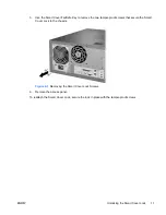
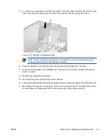
HP Compaq dc7700 MT Скачать руководство пользователя страница 26

7.

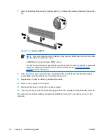
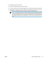
Open both latches of the memory module socket (1), and insert the memory module into the socket
(2).

Figure 2-8

  Installing a DIMM

NOTE

A memory module can be installed in only one way. Match the notch on the module

with the tab on the memory socket.

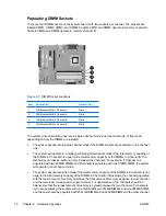
A DIMM must occupy the black XMM1 socket.

For maximum performance, populate the sockets so that the memory capacity is spread as
equally as possible between Channel A and Channel B. Refer to 

Populating DIMM

Sockets

 for more information.

8.

Push the module down into the socket, ensuring that the module is fully inserted and properly
seated. Make sure the latches are in the closed position (3).

9.

Repeat steps 7 and 8 to install any additional modules.

10.

Replace the computer access panel.

11.

Reconnect the power cord and turn on the computer.

12.

Lock any security devices that were disengaged when the computer access panel was removed.

The computer should automatically recognize the additional memory the next time you turn on the
computer.

20

Chapter 2   Hardware Upgrades

ENWW

Содержание Compaq dc7700 MT

Страница 1: ...Hardware Reference Guide dc7700 Series Convertible Minitower HP Compaq Business PC ...

Страница 2: ... and services Nothing herein should be construed as constituting an additional warranty HP shall not be liable for technical or editorial errors or omissions contained herein This document contains proprietary information that is protected by copyright No part of this document may be photocopied reproduced or translated to another language without the prior written consent of Hewlett Packard Compa...

Страница 3: ...manner indicates that failure to follow directions could result in bodily harm or loss of life CAUTION Text set off in this manner indicates that failure to follow directions could result in damage to equipment or loss of information NOTE Text set off in this manner provides important supplemental information ENWW iii ...

Страница 4: ...iv About This Book ENWW ...

Страница 5: ... 12 Replacing the Computer Access Panel 13 Removing the Front Bezel 14 Replacing the Front Bezel 15 Removing Bezel Blanks 16 Installing Additional Memory 17 DIMMs 17 DDR2 SDRAM DIMMs 17 Populating DIMM Sockets 18 Installing DIMMs 19 Removing or Installing an Expansion Card 21 Drive Positions 26 Removing a Drive from a Drive Bay 27 Installing Additional Drives 29 Installing a 5 25 inch or 3 5 inch ...

Страница 6: ...trostatic Discharge Preventing Electrostatic Damage 49 Grounding Methods 49 Appendix E Computer Operating Guidelines Routine Care and Shipping Preparation Computer Operating Guidelines and Routine Care 51 Optical Drive Precautions 52 Operation 52 Cleaning 52 Safety 52 Shipping Preparation 52 Index 53 vi ENWW ...

Страница 7: ...y included on some computer models only Instructions for using the utility are provided in the Troubleshooting Guide on the Documentation and Diagnostics CD NOTE The HP Compaq Convertible Minitower computer can be easily converted to a desktop For more information see the Changing from a Minitower to a Desktop Configuration section in this guide Figure 1 1 Convertible Minitower Configuration ENWW ...

Страница 8: ...r On Light 4 Diskette Drive Activity Light optional 11 USB Universal Serial Bus Ports 5 Diskette Eject Button optional 12 Headphone Connector 6 Hard Drive Activity Light 13 Microphone Connector 7 Optical Drive Eject Buttons NOTE An optical drive is a CD ROM DVD R RW or CD RW DVD Combo drive 1 Some models are configured with a media card reader in the external 3 5 inch drive bay Other models have a...

Страница 9: ...tivity Light 5 CompactFlash I II CompactFlash Card Type 1 CompactFlash Card Type 2 MicroDrive 3 SD MMC miniSD Secure Digital Card SD MiniSD MultiMediaCard MMC Reduced Size MultiMediaCard RS MMC MultiMediaCard 4 0 Mobile Plus Reduced Size MultiMediaCard 4 0 MMC Mobile MMC Micro adapter required MicroSD T Flash adapter required 6 MS PRO MS PRO DUO Memory Stick MS MagicGate Memory Stick MG MagicGate ...

Страница 10: ...RJ 45 Network Connector NOTE Arrangement and number of connectors may vary by model The monitor connector on the system board is inactive when a PCI Express graphics card is installed in the computer If a PCI graphics card is installed the connectors on the card and the system board may be used at the same time Some settings may need to be changed in Computer Setup to use both connectors For infor...

Страница 11: ... move left right up and down using the keyboard instead of the mouse 6 Ctrl Keys Used in combination with another key their effect depends on the application software you are using 7 Application Key1 Used like the right mouse button to open pop up menus in a Microsoft Office application May perform other functions in other software applications 8 Windows Logo Keys1 Used to open the Start menu in M...

Страница 12: ...ns Shift Windows Logo Key m Undoes Minimize All Windows Logo Key e Launches My Computer Windows Logo Key f Launches Find Document Windows Logo Key Ctrl f Launches Find Computer Windows Logo Key F1 Launches Windows Help Windows Logo Key l Locks the computer if you are connected to a network domain or allows you to switch users if you are not connected to a network domain Windows Logo Key r Launches...

Страница 13: ...software applications you are using Serial Number Location Each computer has a unique serial number and a product ID number that are located on the top cover of the computer Keep these numbers available for use when contacting customer service for assistance Figure 1 2 Serial Number and Product ID Location ENWW Special Mouse Functions 7 ...

Страница 14: ...8 Chapter 1 Product Features ENWW ...

Страница 15: ...the power cord in a grounded earthed outlet that is easily accessible at all times To reduce the risk of serious injury read the Safety Comfort Guide It describes proper workstation setup posture and health and work habits for computer users and provides important electrical and mechanical safety information This guide is located on the Web at http www hp com ergo and on the Documentation and Diag...

Страница 16: ...ed order this key before you need one To obtain a FailSafe Key Contact an authorized HP reseller or service provider Order PN 166527 001 for the wrench style key or PN 166527 002 for the screwdriver bit key Refer to the HP Web site http www hp com for ordering information Call the appropriate number listed in the warranty or in the Support Telephone Numbers guide on the Documentation and Diagnosti...

Страница 17: ... proof screws that secure the Smart Cover Lock to the chassis Figure 2 1 Removing the Smart Cover Lock Screws 6 Remove the access panel To reattach the Smart Cover Lock secure the lock in place with the tamper proof screws ENWW Unlocking the Smart Cover Lock 11 ...

Страница 18: ...board as long as the system is plugged into an active AC outlet You must disconnect the power cord to avoid damage to the internal components of the computer 5 Lay the computer down on its large base for greater stability 6 Lift up on the access panel handle 1 slide the access panel back about 1 25 cm 1 2 inch then lift it up and off the unit 2 Figure 2 2 Removing the Computer Access Panel CAUTION...

Страница 19: ...ge base for greater stability 2 Align the tabs on the access panel with the slots on the chassis and push down on the access panel while sliding it forward until it locks into place Figure 2 3 Replacing the Computer Access Panel ENWW Replacing the Computer Access Panel 13 ...

Страница 20: ...ays present on the system board as long as the system is plugged into an active AC outlet You must disconnect the power cord to avoid damage to the internal components of the computer 5 Remove the computer access panel CAUTION After removing the access panel look for the LED on the system board to the right of the DIMM sockets If the LED is illuminated the system still has power Turn off the compu...

Страница 21: ... front bezel in their corresponding slots in the chassis 1 2 Rotate the front bezel onto the chassis 2 3 Snap the catches at the top of the bezel into place 3 4 Snap the release tabs into place 4 Figure 2 5 Replacing the Front Bezel ENWW Replacing the Front Bezel 15 ...

Страница 22: ...ing the access panel look for the LED on the system board to the right of the DIMM sockets If the LED is illuminated the system still has power Turn off the computer and remove the power cord before proceeding 6 Remove the front bezel 7 Gently pull the subpanel with the bezel blanks secured in it away from the front bezel then remove the desired bezel blank CAUTION Hold the subpanel straight when ...

Страница 23: ...or proper system operation the DDR2 SDRAM DIMMs must be industry standard 240 pin unbuffered PC2 4300 533 MHz compliant PC2 5300 667 MHz compliant or PC2 6400 800 MHz compliant 1 8 volt DDR2 SDRAM DIMMs The DDR2 SDRAM DIMMs must also support CAS latency 4 DDR2 533 MHz and DDR2 667 MHz and CAS latency 5 DDR2 667 MHz and DDR2 800 MHz contain the mandatory JEDEC SPD information In addition the comput...

Страница 24: ...the DIMMs in Channel A is equal to the total memory capacity of the DIMMs in Channel B The technology and device width can vary between the channels For example if Channel A is populated with two 256MB DIMMs and Channel B is populated with one 512MB DIMM the system will operate in dual channel mode The system will operate in flex mode if the total memory capacity of the DIMMs in Channel A is not e...

Страница 25: ... cards Before beginning these procedures ensure that you are discharged of static electricity by briefly touching a grounded metal object For more information refer to Appendix D Electrostatic Discharge When handling a memory module be careful not to touch any of the contacts Doing so may damage the module 1 Remove disengage any security devices that prohibit opening the computer 2 Remove all remo...

Страница 26: ...el A and Channel B Refer to Populating DIMM Sockets for more information 8 Push the module down into the socket ensuring that the module is fully inserted and properly seated Make sure the latches are in the closed position 3 9 Repeat steps 7 and 8 to install any additional modules 10 Replace the computer access panel 11 Reconnect the power cord and turn on the computer 12 Lock any security device...

Страница 27: ...include an optional PCI extender that adds two PCI expansion slots to the board for a total of four PCI expansion slots You can install a PCI Express x1 x4 x8 or x16 expansion card in the PCI Express x16 expansion slot To remove replace or add an expansion card 1 Remove disengage any security devices that prohibit opening the computer 2 Remove all removable media such as diskettes or compact discs...

Страница 28: ... DIMM sockets If the LED is illuminated the system still has power Turn off the computer and remove the power cord before proceeding 6 Locate the correct vacant expansion socket on the system board and the corresponding expansion slot on the back of the computer chassis 7 Push down and out on the two green thumb tabs inside the chassis and rotate the expansion card retention latch up Figure 2 10 O...

Страница 29: ... Lift the expansion slot cover from the expansion slot Figure 2 11 Removing an Expansion Slot Cover b If you are removing a standard PCI card hold the card at each end and carefully rock it back and forth until the connectors pull free from the socket Lift the card straight up to remove it Be sure not to scrape the card against other components Figure 2 12 Removing a Standard PCI Expansion Card EN...

Страница 30: ...sure not to scrape the card against other components Figure 2 13 Removing a PCI Express x16 Expansion Card 9 Store the removed card in anti static packaging 10 If you are not installing a new expansion card install an expansion slot cover to close the open slot CAUTION After removing an expansion card you must replace it with a new card or expansion slot cover for proper cooling of internal compon...

Страница 31: ...ion card retention latch making sure that it snaps firmly into place 13 Connect external cables to the installed card if needed Connect internal cables to the system board if needed 14 Replace the computer access panel 15 Reconnect the power cord and turn on the computer 16 Lock any security devices that were disengaged when the computer access panel was removed 17 Reconfigure the computer if nece...

Страница 32: ...racket for these drive bays is available from HP 2 Depending on the computer configuration you may have a bezel blank in this position If you do not have a drive in this slot you may choose to install a 3 5 inch drive such as a diskette drive hard drive or media card reader later on To verify the type and size of the storage devices installed in the computer run Computer Setup Refer to the Compute...

Страница 33: ...ord to avoid damage to the internal components of the computer 5 Remove the computer access panel CAUTION After removing the access panel look for the LED on the system board to the right of the DIMM sockets If the LED is illuminated the system still has power Turn off the computer and remove the power cord before proceeding 6 Remove the front bezel 7 Disconnect the power and data cables on the ba...

Страница 34: ...e 2 17 Removing a 3 5 inch Drive or a 5 25 inch Drive in the Minitower Configuration Optical Drive shown To remove a hard drive from and internal 3 5 inch drive bay pull up on the green hard drive drivelock mechanism 1 for that drive and slide the drive from the drive bay 2 Figure 2 18 Removing a Hard Drive 9 Store the removed drive in anti static packaging 28 Chapter 2 Hardware Upgrades ENWW ...

Страница 35: ...P has provided extra guide screws installed on the chassis The hard drive uses 6 32 standard screws four of which are installed on the hard drive bracket under the access panel All other drives use M3 metric screws eight of which are installed on the diskette drive bracket under the access panel The HP supplied metric screws are black The HP supplied standard screws are silver CAUTION To prevent l...

Страница 36: ...operating system then turn off any external devices 4 Disconnect the power cord from the power outlet and disconnect any external devices CAUTION Regardless of the power on state voltage is always present on the system board as long as the system is plugged into an active AC outlet You must disconnect the power cord to avoid damage to the internal components of the computer 5 Remove the computer a...

Страница 37: ... locks 2 The drivelock automatically secures the drive in the bay CAUTION The bottom 5 25 inch drive bay has a shorter depth than the upper two bays The bottom bay supports a drive that is no more than 17 cm 6 7 inches in depth including the cables that attach to the back of the drive Do not try to force a larger drive such as an optical drive into the bottom bay This could cause damage to the dri...

Страница 38: ...e system board labeled FLOPPY P10 If your are installing a media card reader install the PCI card included with the media card reader and connect the USB cable from the media card reader to the USB connector on the PCI card 11 Remove the appropriate bezel blank from the subpanel inside the front bezel See the Removing Bezel Blanks section for more information 12 Replace the front bezel and compute...

Страница 39: ...ble media such as diskettes or compact discs from the computer 3 Turn off the computer properly through the operating system then turn off any external devices 4 Disconnect the power cord from the power outlet and disconnect any external devices CAUTION Regardless of the power on state voltage is always present on the system board as long as the system is plugged into an active AC outlet You must ...

Страница 40: ...and data cable 2 to the rear of the hard drive Figure 2 23 Connecting the Power Cable and Data Cable to a SATA Hard Drive 9 Connect the opposite end of the data cable to the appropriate system board connector NOTE If your system has only one SATA hard drive you must connect the hard drive data cable to the dark blue connector labeled SATA0 to avoid any hard drive performance problems If you are ad...

Страница 41: ...Documentation and Diagnostics CD for instructions about using Computer Setup NOTE If you replaced the primary hard drive use the Restore Plus CD set that you created when you initially set up the computer to restore the operating system software drivers and any software applications that were preinstalled on the computer When the restore process has completed reinstall any personal files that you ...

Страница 42: ... avoid damage to the internal components of the computer 5 Remove the computer access panel CAUTION After removing the access panel look for the LED on the system board to the right of the DIMM sockets If the LED is illuminated the system still has power Turn off the computer and remove the power cord before proceeding 6 Remove the front bezel 7 Disconnect all power and data cables from the back o...

Страница 43: ... into the bottom bay This could cause damage to the drive and the system board The use of unnecessary force when installing any drive into the drive bay may result in damage to the drive 11 Reconnect all power and data cables to the drives in the 5 25 inch drive bays 12 Remove the bezel subpanel as described in the Removing Bezel Blanks section CAUTION Hold the subpanel straight when you pull it a...

Страница 44: ...m board as long as the system is plugged into an active AC outlet You must disconnect the power cord to avoid damage to the internal components of the computer 5 Remove the computer access panel CAUTION After removing the access panel look for the LED on the system board to the right of the DIMM sockets If the LED is illuminated the system still has power Turn off the computer and remove the power...

Страница 45: ...cluding the cables that attach to the back of the drive Do not try to force a larger drive such as an optical drive into the bottom bay This could cause damage to the drive and the system board The use of unnecessary force when installing any drive into the drive bay may result in damage to the drive 11 Reconnect all power and data cables to the drives in the 5 25 inch drive bays 12 Remove the bez...

Страница 46: ...l Figure 2 29 Changing from a Desktop to a Minitower Configuration 15 Replace the front bezel and computer access panel 16 Reconnect the power cord and turn on the computer 17 Lock any security devices that were disengaged when the computer access panel was removed 40 Chapter 2 Hardware Upgrades ENWW ...

Страница 47: ...nly 100 lb 45 5 kg Temperature Range Operating Nonoperating 50 to 95 F 22 to 140 F 10 to 35 C 30 to 60 C Relative Humidity noncondensing Operating Nonoperating 38 7 C max wet bulb 10 90 5 95 10 90 5 95 Maximum Altitude unpressurized Operating Nonoperating 10 000 ft 30 000 ft 3048 m 9144 m NOTE Operating temperature is derated 1 0 C per 300 m 1000 ft to 3000 m 10 000 ft above sea level no direct su...

Страница 48: ...rrent maximum 1 6A 100 VAC 3A 200 VAC 1 This system utilizes an active power factor corrected power supply This allows the system to pass the CE mark requirements for use in the countries of the European Union The active power factor corrected power supply also has the added benefit of not requiring an input voltage range select switch 42 Appendix A Specifications ENWW ...

Страница 49: ...tings Static electricity can damage the electronic components of the computer or optional equipment Before beginning these procedures ensure that you are discharged of static electricity by briefly touching a grounded metal object NOTE The lifetime of the lithium battery can be extended by plugging the computer into a live AC wall socket The lithium battery is only used when the computer is NOT co...

Страница 50: ...ternal component to gain access to the battery 7 Depending on the type of battery holder on the system board complete the following instructions to replace the battery Type 1 a Lift the battery out of its holder Figure B 1 Removing a Coin Cell Battery Type 1 b Slide the replacement battery into position positive side up The battery holder automatically secures the battery in the proper position Ty...

Страница 51: ...t the new battery and position the clip back into place Figure B 3 Removing a Coin Cell Battery Type 3 NOTE After the battery has been replaced use the following steps to complete this procedure 8 Replace the computer access panel 9 Plug in the computer and turn on power to the computer 10 Reset the date and time your passwords and any special system setups using Computer Setup Refer to the Comput...

Страница 52: ...46 Appendix B Battery Replacement ENWW ...

Страница 53: ...Management Guide on the Documentation and Diagnostics CD and the HP ProtectTools Security Manager Guide some models at http www hp com Installing a Security Lock The security locks displayed below and on the following page can be used to secure the computer Cable Lock Figure C 1 Installing a Cable Lock ENWW Installing a Security Lock 47 ...

Страница 54: ...Padlock Figure C 2 Installing a Padlock 48 Appendix C External Security Devices ENWW ...

Страница 55: ...everal methods for grounding Use one or more of the following methods when handling or installing electrostatic sensitive parts Use a wrist strap connected by a ground cord to a grounded workstation or computer chassis Wrist straps are flexible straps with a minimum of 1 megohm 10 percent resistance in the ground cords To provide proper ground wear the strap snug against the skin Use heelstraps to...

Страница 56: ...50 Appendix D Electrostatic Discharge ENWW ...

Страница 57: ...k computers on top of each other or place computers so near each other that they are subject to each other s re circulated or preheated air If the computer is to be operated within a separate enclosure intake and exhaust ventilation must be provided on the enclosure and the same operating guidelines listed above will still apply Keep liquids away from the computer and keyboard Never cover the vent...

Страница 58: ...r and have it checked by an authorized HP service provider Shipping Preparation Follow these suggestions when preparing to ship the computer 1 Back up the hard drive files on PD discs tape cartridges CDs or diskettes Be sure that the backup media is not exposed to electrical or magnetic impulses while stored or in transit NOTE The hard drive locks automatically when the system power is turned off ...

Страница 59: ...ard drive installing 33 removing 27 restoring software 35 headphone connector 2 I installation guidelines 9 installing battery 43 diskette drive 30 drive cables 29 expansion card 21 guide screws 29 hard drive 33 media card reader 30 memory 17 optical drive 30 restore software 35 security locks 47 K keyboard components 5 connector 4 L line in connector 4 line out connector 4 locks cable lock 47 pad...

Страница 60: ...ard reader 27 PCI card 23 PCI Express card 24 Smart Cover Lock 10 S security cable lock 47 padlock 48 Smart Cover Lock 10 serial connector 4 serial number location 7 shipping preparation 52 Smart Cover Lock 10 specifications computer 41 memory 17 U unlocking access panel 10 47 USB ports front panel 2 rear panel 4 V ventilation guidelines 51 W Windows Logo key 6 54 Index ENWW ...

Отзывы: