background image

2.

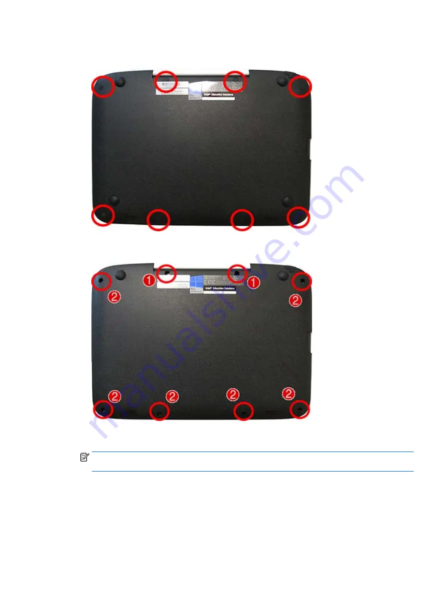
Remove the 8 rubber screw covers from atop the screws. The screw covers are different sizes based on

location, so be sure to make note of each screw covers location for replacement.

3.

Remove the 2 Phillips M2.5×8.0 screws and 6 Phillips M2.5×6.0 screws that secure the bottom cover to

the computer.

4.

Starting at the card reader slot, pry around the seams of the bottom cover to disengage it from the

computer.

NOTE:

The bottom cover may be secured very tightly to the computer and may require significant

force to remove.

Reverse this procedure to install the bottom cover.

Component replacement procedures

23

Содержание Classmate

Страница 1: ...HP Classmate Notebook Maintenance and Service Guide IMPORTANT This document is intended for HP authorized service providers only ...

Страница 2: ... services are set forth in the express warranty statements accompanying such products and services Nothing herein should be construed as constituting an additional warranty HP shall not be liable for technical or editorial errors or omissions contained herein First Edition June 2014 Document Part Number 760165 001 Product notice This guide describes features that are common to most models Some fea...

Страница 3: ...llow another hard surface such as an adjoining optional printer or a soft surface such as pillows or rugs or clothing to block airflow Also do not allow the AC adapter to contact the skin or a soft surface such as pillows or rugs or clothing during operation The computer and the AC adapter comply with the user accessible surface temperature limits defined by the International Standard for Safety o...

Страница 4: ...iv Safety warning notice ...

Страница 5: ... replacement procedures preliminary requirements 17 Tools required 17 Service considerations 17 Plastic parts 17 Cables and connectors 18 Drive handling 18 Grounding guidelines 19 Electrostatic discharge damage 19 Packaging and transporting guidelines 20 Workstation guidelines 20 Equipment guidelines 21 5 Removal and replacement procedures for Authorized Service Provider parts 22 Component replace...

Страница 6: ...verything and reinstalling Windows 56 Backing up data using File History 56 7 Specifications 57 Computer specifications 57 25 7 cm 10 1 in display specifications 58 Hard drive specifications 59 Specification information in Device Manager 59 8 Statement of Volatility 60 Non volatile memory usage 62 Questions and answers 64 9 Power cord set requirements 65 Requirements for all countries and regions ...

Страница 7: ...0 hard drives Supports the following drives 320 GB 5400 rpm Webcam microphone audio Integrated HD camera 1 0 MP Built in speakers 2 Ethernet Realtek RTL8105E VL 10 100 Ethernet Wireless Integrated WLAN by way of wireless module LiteOn AzureWave 802 11 b g n 1x1 BT 4 0 combo External media card Digital Media Reader Slot Supports SDHC Ports Headphone Microphone Thermal probe combo jack RJ 45 Etherne...

Страница 8: ...anguage EM Windows 8 1 Small Screen Language Restore Media DRDVD Windows 8 1 64 bit drivers only NOTE Portable optical drive required to use restore media Restore Media SRDVD Windows 8 1 64 bit drivers only NOTE Portable optical drive required to use restore media Web only support Windows 8 1 Professional 64 Windows 8 1 Enterprise 64 Certified Microsoft WHQL Serviceability End user replaceable par...

Страница 9: ...utton briefly to initiate Sleep When the computer is in the Sleep state press the button briefly to exit Sleep When the computer is in Hibernation press the button briefly to exit Hibernation CAUTION Pressing and holding down the power button will result in the loss of unsaved information If the computer has stopped responding and Windows shutdown procedures are ineffective press and hold the powe...

Страница 10: ... computer is connected to external power and the battery is charged from 90 to 99 percent Amber The computer is connected to external power and the battery is charged from 0 to 89 percent Off The battery is fully charged 8 Touchpad Moves the pointer and selects or activates items on the screen 9 Windows key Returns you to the Start screen from an open app or the Windows desktop NOTE Pressing the W...

Страница 11: ...shandled or stolen 14 USB 3 0 port identifying Connects an optional USB device such as a keyboard mouse external drive printer scanner or USB hub 15 HDMI port Connects an optional video or audio device such as a high definition television any compatible digital or audio component or a high speed HDMI device 16 Memory card reader Reads optional memory cards that store manage share or access informa...

Страница 12: ... a headset WARNING To reduce the risk of personal injury adjust the volume before putting on headphones earbuds or a headset For additional safety information see the Regulatory Safety and Environmental Notices To access this guide from the Start screen type support and then select the HP Support Assistant app NOTE When a device is connected to the jack the computer speakers are disabled 6 Chapter...

Страница 13: ...omponent Description 19 Power connector Connects an AC adapter 20 RJ 45 network jack lights Connects a network cable Green right The network is connected Amber left Activity is occurring on the network Rear 7 ...

Страница 14: ...ded on the service tag Serial 1 This is an alphanumeric identifier that is unique to each product Product name 2 This is the product name affixed to the front of the computer Warranty period 3 This number describes the duration in years of the warranty period for the computer 8 Chapter 2 External component identification ...

Страница 15: ...upported parts for your computer go to http partsurfer hp com select your country or region and then follow the on screen instructions NOTE Details about your computer including model serial number product key and length of warranty are on the service tag at the bottom of your computer See Service tag on page 8 for details Computer major components 9 ...

Страница 16: ...mber Whole unit replacement Latin America 762412 001 The United Kingdom 762411 001 The United States 762410 001 1 Top cover includes touchpad and handle kit 764406 001 2 Keyboard includes cable 10 Chapter 3 Illustrated parts catalog ...

Страница 17: ...d 764413 001 5 Heat sink includes replacement thermal material 764414 001 6 Battery 3 cell 34 Wh 3 4 Ah polymer battery 786031 001 7 Memory modules PC3L 12800 1600 MHz DDR3L 2 GB 691739 005 8 Speaker assembly 764411 001 9 WLAN module LiteOn AzureWave 802 11 b g n 1x1 BT 4 0 combo 788292 001 10 Power connector and cable 764410 001 11 RTC battery 764403 001 12 Base enclosure 764415 001 Computer majo...

Страница 18: ...l raw 778821 001 2 Display bezel 778822 001 3 Display Hinge Kit includes left and right hinges 764405 001 4 Webcam module 778819 001 5 Display hinge cover 764416 001 6 Display rear cover 778818 001 7 Display panel frame 778820 001 12 Chapter 3 Illustrated parts catalog ...

Страница 19: ...Cable Kit Item Description Spare part number Cable Kit 764412 001 1 Touchpad cable 2 Narrow flat ribbon cable 3 Wide flat ribbon cable Cable Kit 13 ...

Страница 20: ...r 1 Hard drives 320 GB 5400 rpm 7 mm 786030 001 Hard Drive Hardware Kit includes 764408 001 2 Hard drive bracket 3 Rubber rails Sponge not illustrated Screws not illustrated 4 Hard drive connector cable 764409 001 14 Chapter 3 Illustrated parts catalog ...

Страница 21: ...d and handle kit 764408 001 Hard Drive Hardware Kit includes hard drive bracket rubber rails sponge and screws 764409 001 Hard drive connector cable 764410 001 Power connector and cable 764411 001 Speaker assembly 764412 001 Cable Kit see Cable Kit on page 13 for more Cable Kit spare part information 764413 001 I O board 764414 001 Heat sink includes replacement thermal material 764415 001 Base en...

Страница 22: ...s 778823 161 Keyboard for use in Latin America 778821 001 Display panel raw 780744 001 Screw Kit 786030 001 320 GB 5400 rpm 7 mm hard drive 786031 001 3 cell 37 WHr 3 4 Ah Li ion battery 788292 001 802 11b g n 1x1 WiFi Adapter Bluetooth 4 0 16 Chapter 3 Illustrated parts catalog ...

Страница 23: ...clude some of the considerations that you must keep in mind during disassembly and assembly procedures NOTE As you remove each subassembly from the computer place the subassembly and all accompanying screws away from the work area to prevent damage Plastic parts CAUTION Using excessive force during disassembly and reassembly can damage plastic parts Use care when handling the plastic parts Apply p...

Страница 24: ...d drive shut down the computer If you are unsure whether the computer is off or in Hibernation turn the computer on and then shut it down through the operating system Before handling a drive be sure that you are discharged of static electricity While handling a drive avoid touching the connector Before removing a diskette drive or optical drive be sure that a diskette or disc is not in the drive a...

Страница 25: ...recautions Keep components in their electrostatic safe containers until you are ready to install them Use nonmagnetic tools Before touching an electronic component discharge static electricity by using the guidelines described in this section Avoid touching pins leads and circuitry Handle electronic components as little as possible If you remove a component place it in an electrostatic safe contai...

Страница 26: ...er materials are selected to avoid static charging When grounding is not possible use an ionizer to dissipate electric charges Workstation guidelines Follow these grounding workstation guidelines Cover the workstation with approved static shielding material Use a wrist strap connected to a properly grounded work surface and use properly grounded tools and equipment Use conductive field service too...

Страница 27: ...istance between the operator and ground To be effective the conductive strips must be worn in contact with the skin The following grounding equipment is recommended to prevent electrostatic damage Antistatic tapes Antistatic smocks aprons and sleeve protectors Conductive bins and other assembly or soldering aids Nonconductive foam Conductive tabletop workstations with ground cords of one megohm re...

Страница 28: ...val and replacement procedures for Authorized Service Provider only parts There are as many as 58 screws and 6 nuts that must be removed replaced or loosened when servicing Authorized Service Provider only parts Make special note of each screw size and location during removal and replacement Bottom cover Description Spare part number Bottom cover 746415 001 Before removing the bottom cover follow ...

Страница 29: ...ips M2 5 8 0 screws and 6 Phillips M2 5 6 0 screws that secure the bottom cover to the computer 4 Starting at the card reader slot pry around the seams of the bottom cover to disengage it from the computer NOTE The bottom cover may be secured very tightly to the computer and may require significant force to remove Reverse this procedure to install the bottom cover Component replacement procedures ...

Страница 30: ...hen click Next 6 Under Step 2 Select a Download click the BIOS link 7 Click the link for the most recent BIOS 8 Click the Download button and then follow the on screen instructions Before removing the memory module follow these steps 1 Shut down the computer If you are unsure whether the computer is off or in Hibernation turn the computer on and then shut it down through the operating system 2 Dis...

Страница 31: ...of the module opposite the slot rises away from the computer 2 Remove the memory module 2 by pulling the module away from the slot at an angle NOTE Memory modules are designed with a notch to prevent incorrect insertion into the memory module slot Reverse this procedure to install a memory module Component replacement procedures 25 ...

Страница 32: ...power from the computer by first unplugging the power cord from the AC outlet and then unplugging the AC adapter from the computer 4 Remove the bottom cover see Bottom cover on page 22 5 Disconnect the battery cable from the system board Remove the WLAN module 1 Disconnect the WLAN antenna cables 1 from the terminals on the WLAN module NOTE The WLAN antenna cable labeled 1 connects to the WLAN mod...

Страница 33: ...notch to prevent incorrect insertion NOTE If the WLAN antennas are not connected to the terminals on the WLAN module the protective sleeves must be installed on the antenna connectors as shown in the following illustration Reverse this procedure to install the WLAN module Component replacement procedures 27 ...

Страница 34: ...es connected to the computer 3 Disconnect the power from the computer by first unplugging the power cord from the AC outlet and then unplugging the AC adapter from the computer 4 Remove the bottom cover see Bottom cover on page 22 5 Disconnect the battery cable from the system board Remove the keyboard 1 Position the computer upright and open as far as possible 2 Using a small thin tool press the ...

Страница 35: ...3 Lift the top of the keyboard upward 2 and place the keyboard on the palm rest 4 Disconnect the keyboard cable from the system board Component replacement procedures 29 ...

Страница 36: ...nector is located on the bottom of the system board along with the keyboard connector Disconnect the touchpad cable if you need remove the system board Reverse this procedure to install the keyboard 30 Chapter 5 Removal and replacement procedures for Authorized Service Provider parts ...

Страница 37: ... all external devices connected to the computer 3 Disconnect the power from the computer by first unplugging the power cord from the AC outlet and then unplugging the AC adapter from the computer 4 Remove the bottom cover see Bottom cover on page 22 5 Disconnect the battery cable from the system board Remove the speaker assembly 1 Disconnect the speaker cable from the system board 1 2 Remove the 2...

Страница 38: ...tape that secure the speaker cable to the computer 3 and then remove the speakers Reverse this procedure to install the speaker assembly 32 Chapter 5 Removal and replacement procedures for Authorized Service Provider parts ...

Страница 39: ...the power from the computer by first unplugging the power cord from the AC outlet and then unplugging the AC adapter from the computer 4 Remove the bottom cover see Bottom cover on page 22 5 Disconnect the battery cable from the system board Remove the heat sink assembly 1 Remove the tape 1 that secures the antenna cables atop the heat sink and remove the antenna cables from the heat sink 2 In the...

Страница 40: ...es of the system board components and the heat sink each time you remove the heat sink All heat sink and processor spare part kits include thermal material Reverse this procedure to install the heat sink assembly 34 Chapter 5 Removal and replacement procedures for Authorized Service Provider parts ...

Страница 41: ... the computer 3 Disconnect the power from the computer by first unplugging the power cord from the AC outlet and then unplugging the AC adapter from the computer 4 Remove the bottom cover see Bottom cover on page 22 5 Disconnect the battery cable from the system board Remove the power cable 1 Disconnect the cable from the system board 1 and lift the cable from between the hard drive and the batter...

Страница 42: ...3 Lift the power cable from the computer 4 Reverse this procedure to install the power cable 36 Chapter 5 Removal and replacement procedures for Authorized Service Provider parts ...

Страница 43: ...ugh the operating system 2 Disconnect all external devices connected to the computer 3 Disconnect the power from the computer by first unplugging the power cord from the AC outlet and then unplugging the AC adapter from the computer 4 Remove the bottom cover see Bottom cover on page 22 5 Disconnect the battery cable from the system board To remove a hard drive 1 Remove the 4 Phillips PM2 0 3 0 scr...

Страница 44: ...llips PM2 5 3 0 screws 1 that secure the cover to the drive and then lift the cover off the drive 2 6 Pull the hard drive cable to disconnect it from the drive 3 NOTE You must remove the bracket before you can remove the cable 38 Chapter 5 Removal and replacement procedures for Authorized Service Provider parts ...

Страница 45: ...remove the rubber rails from the hard drive pull each rail off to disengage the adhesive that secures the rail to the drive Reverse this procedure to install a hard drive Component replacement procedures 39 ...

Страница 46: ... power from the computer by first unplugging the power cord from the AC outlet and then unplugging the AC adapter from the computer 4 Remove the bottom cover see Bottom cover on page 22 Remove the battery 1 Remove the 2 Phillips M2 0 6 0 screws 1 that secure the battery to the computer 2 Lift the tape from atop the battery connector and then disconnect the cable from the system board connector 2 3...

Страница 47: ...pter from the computer 4 Remove the bottom cover see Bottom cover on page 22 5 Remove the battery see Battery on page 40 6 Remove the hard drive see Hard drive on page 37 Remove the I O board 1 Disconnect the following cables from the I O board 1 Display cable 2 Narrow ribbon cable 3 Speaker cable 4 Wide ribbon cable 2 Remove the Phillips PM2 0 5 5 screw 5 that secures the board to the computer 3 ...

Страница 48: ...ottom cover on page 22 5 Remove the battery see Battery on page 40 6 Remove the hard drive see Hard drive on page 37 7 Remove the keyboard see Keyboard on page 28 and disconnect the touchpad cable from the connector located under the keyboard When replacing the system board be sure to remove the following components from the defective system board and install on the replacement system board Memory...

Страница 49: ...2 that secure the system board to the computer 3 Pull the system board away from the side of the computer to release the connectors and then remove it from the computer Reverse this procedure to install the system board Component replacement procedures 43 ...

Страница 50: ...nplugging the AC adapter from the computer 4 Remove the bottom cover see Bottom cover on page 22 5 Remove the battery see Battery on page 40 6 Remove the hard drive see Hard drive on page 37 7 Remove the keyboard see Keyboard on page 28 and disconnect the touchpad cable from the connector located under the keyboard 8 Remove the system board see System board on page 42 Remove the RTC battery 1 Posi...

Страница 51: ...4 Lift the battery to disengage it from the adhesive that secures it to the system board 3 Reverse this procedure to install the RTC battery Component replacement procedures 45 ...

Страница 52: ...ed to the computer 3 Disconnect the power from the computer by first unplugging the power cord from the AC outlet and then unplugging the AC adapter from the computer 4 Remove the bottom cover see Bottom cover on page 22 5 Disconnect the battery cable from the system board Remove the display assembly 1 Remove the following 1 2 round rubber screw covers near the webcam 2 2 rubber screw covers near ...

Страница 53: ...2 Remove the 2 Phillips PM2 5 5 0 screws 1 and the 6 Phillips PM2 5 4 0 screws 2 that secure the display rear cover to the display bezel Component replacement procedures 47 ...

Страница 54: ...first move the webcam by removing the 2 Phillips PM2 0 3 0 screws 1 that secure the webcam to the display lift the webcam cables to disengage the adhesive that secures them to the display 2 and lay the connected webcam aside 5 Lift the tape that secures the wireless transceivers to the sides of the display 3 48 Chapter 5 Removal and replacement procedures for Authorized Service Provider parts ...

Страница 55: ...he display panel to the display 4 7 Remove the 4 Phillips PM2 5 4 0 screws 1 that secure the display panel to the bezel 8 Lift the tape over the display panel connector 2 and disconnect the cable from the panel 3 Component replacement procedures 49 ...

Страница 56: ...t secure the panel to the frame and then lift the panel from the frame The display panel is available using spare part number 778821 001 The display panel frame is available using spare part number 778820 001 50 Chapter 5 Removal and replacement procedures for Authorized Service Provider parts ...

Страница 57: ...ver by prying the cover off with a thin tool The display hinge cover is available using spare part number 764416 001 12 To remove the display assembly remove the 4 Phillips PM2 0 3 0 screws 1 that secure the display to the hinges and then rotate the hinges upward 2 to allow enough room to remove the display from the hinges Component replacement procedures 51 ...

Страница 58: ...le from the display to disengage the adhesive 2 lift the tape that secures the cables to the display 3 and then remove the webcam The webcam module is available using spare part number 778819 001 16 If you need to replace the bezel or antennas remove the display panel from the bezel see step 8 and then remove the antennas from the bezel as follows 52 Chapter 5 Removal and replacement procedures fo...

Страница 59: ...spare part number 778822 001 CAUTION When installing the display assembly be sure that the wireless antenna cables are routed and arranged properly Failure to properly route the antennas can result in degradation of the computer s wireless performance 17 If you need to remove the hinges on the bottom of the computer remove the 2 Phillips PM2 5 5 0 screws that secure the hinges to the computer Comp...

Страница 60: ...e computer and then lift the hinges from the computer 2 Display hinges are available in the Display Hinge Kit using spare part number 764405 001 Reverse this procedure to reassemble and install the display assembly 54 Chapter 5 Removal and replacement procedures for Authorized Service Provider parts ...

Страница 61: ...er create a Microsoft recovery drive The MS recovery drive backs up the recovery partition on the computer and ensure access to the Refresh your PC and Remove everything and reinstall Windows options even if the recovery partition on the computer has been corrupted or removed NOTE On select models a recovery drive can be created on a USB flash drive purchased separately A micro USB to USB adapter ...

Страница 62: ...is section provides a speedy simple way to return the computer to its original state This option removes all personal data apps and settings from your computer and reinstalls Windows IMPORTANT This option does not provide backups of your information Before using this option back up any personal information you wish to retain You can initiate this option from the Start screen 1 On the Start screen ...

Страница 63: ...put 19V Temperature Operating 5 C to 35 C 41 F to 95 F Nonoperating 20 C to 60 C 4 F to 140 F Relative humidity Operating 10 to 90 Nonoperating 5 to 95 Maximum altitude unpressurized Operating 14 7 to 10 1 psia 15 m to 3 048 m 50 ft to 10 000 ft Nonoperating 14 7 to 4 4 psia 15 m to 12 192 m 50 ft to 40 000 ft Shock Operating 40 g 2 ms half sine Nonoperating 200 g 2 ms half sine Random vibration O...

Страница 64: ...ve area 8 75x4 91 in 222 22 x124 81 mm PPI 150 Surface treatment Anti glare Contrast ratio 600 1 typical Refresh rate 60 Hz Brightness 400 nits typical Viewing angle UWVA 85 85 85 85 Backlight LED Pixel resolution Pitch 0 1695mm 0 1695 mm Format 1280 x 800 WXGA Configuration RGB Stripe 58 Chapter 7 Specifications ...

Страница 65: ...ifications may differ slightly NOTE Certain restrictions and exclusions apply Contact technical support for details Specification information in Device Manager Device Manager allows you to view and control the hardware attached to the computer as well as provides hardware specification information You can also add hardware or modify device configurations using Device Manager After you open Device ...

Страница 66: ...r BIOS F10 Setup by powering on the system and pressing F10 when prompted near the bottom of the display or press the ESC key to display the start up menu then press F10 If the system has a BIOS administrator password enter the password at the prompt b Select the File menu then Restore Defaults c Select the System Configuration menu then Restore Security Defaults d If an asset or ownership tag is ...

Страница 67: ...eally is U S Department of Defense DOD 5220 22 M approved To run HP Disk Sanitizer enter BIOS Setup by powering on the system and pressing F10 when prompted near the bottom of the display or press ESC to display the start up menu then press F10 Select the Security menu and scroll down to the Utilities menu Select Disk Sanitizer and select the desired drive For a higher level of protection select O...

Страница 68: ...ial Presence Detect SPD configuration data 256 Bytes per memory module 128 Bytes programma bl e not customer accessible No Yes Stores memory module information Programmed by the memory vendor Data cannot be written to this memory when the module is installed in a PC The specific write protection method varies by memory vendor System BIOS 4 to 5 MBytes Yes Yes Store system BIOS code and PC configur...

Страница 69: ...n and calibration data Programmed at the factory Tools for writing data to this memory are not made public A utility is required for writing data to this memory and is typically not made available to the public unless a firmware upgrade is necessary to address a unique issue Web camera 64K bit No Yes Store Web Cam configuration and firmware Using a utility from the device manufacturer that can be ...

Страница 70: ...to read SPD memory 3 Does the Firmware Hub for System BIOS contain the BIOS program Is this chip writable and if so how The Firmware Hub does contain the BIOS program and is writable A utility is required to perform the write function 4 In some PC systems the Firmware Hub for System BIOS is a flash memory chip so that updates can be written by the customer Is this true for these BIOS chips Yes the...

Страница 71: ...t All power cord sets must be approved by an acceptable accredited agency responsible for evaluation in the country or region where the power cord set will be used The power cord sets must have a minimum current capacity of 10 A and a nominal voltage rating of 125 or 250 V ac as required by the power system of each country or region The appliance coupler must meet the mechanical configuration of a...

Страница 72: ... must bear a T mark and registration number in accordance with the Japanese Dentori Law The flexible cord must be Type VCTF 3 conductor 0 75mm2 or 1 25mm2 conductor size The wall plug must be a two pole grounding type with a Japanese Industrial Standard C8303 7 A 125 V ac configuration 4 The flexible cord must be Type RVV 3 conductor 0 75mm2 conductor size Power cord set fittings appliance coupler...

Страница 73: ...he battery in general household waste Follow the local laws and regulations in your area for battery disposal HP encourages customers to recycle used electronic hardware HP original print cartridges and rechargeable batteries For more information about recycling programs see the HP Web site at http www hp com recycle 67 ...

Страница 74: ... rear cover spare part number 12 15 display specifications 58 drives preventing damage 18 E electrostatic discharge 19 Ethernet product description 1 external media cards product description 1 F File History 56 G graphics product description 1 grounding equipment and methods 21 H hard drive precautions 18 product description 1 removing 37 spare part numbers 14 16 specifications 59 hard drive compo...

Страница 75: ...ider 22 remove everything and reinstall Windows 56 reset steps 56 RJ 45 network jack identifying 7 RJ 45 network lights identifying 7 RTC battery removal 44 spare part number 11 15 44 S Screw Kit spare part number 15 security cable slot identifying 5 security product description 2 service considerations 17 service tag 8 serviceability product description 2 slots security cable 5 speaker assembly r...

Отзывы: