background image

Recovering the Chrome operating system

To recover the Chrome operating system on your computer using the recovery media you created:

1.

Disconnect any external devices connected to the computer, plug in the power cord, and then turn on 
the computer.

2.

To enter recovery mode, press and hold 

esc

+

f3

, and then press the power button. When the “Chrome OS is 

missing or damaged” screen displays, insert the recovery media into the computer. The recovery process 
begins immediately.

3.

Wait while Chrome verifies the integrity of the recovery media.

NOTE:

If you need to cancel the recovery during the verification process, press and hold the power button 

until the computer turns off. Do not disrupt the system recovery process after the verification step is 
complete.

NOTE:

If an error message appears, you might need to run the Chrome Recovery Utility again, or use a 

different USB flash drive or SD memory card.

4.

When the “System Recovery is complete” message appears, remove the recovery media.

The computer restarts with Chrome OS reinstalled.

Setting up the computer after a reset or recovery

After a reset or recovery is complete, perform the initial setup process. For details on setting up the computer, 
go to 

http://www.support.google.com

.

Erase and format the recovery media

During the process of creating recovery media, the USB flash drive or SD memory card is formatted for use as a 
recovery tool. After you recover your computer, you will need to erase the recovery media if you want to reuse 
your USB flash drive or SD memory card to store other files. Use the steps in this section to erase the recovery 
media using the Chromebook Recovery Utility.

1.

Click the Launcher icon, and then click All Apps.

2.

In the apps window, click Recovery.

3.

Click the Settings icon, and then click Erase recovery media.

4.

Select the USB flash drive or SD memory card you inserted, click Continue, and then click Erase now.

5.

After the recovery media is erased, click Done to close the Chromebook Recovery Utility, and then remove 
the USB flash drive or SD memory card.

The media is ready to be formatted with a formatting tool provided by your operating system.

46

Chapter 6   Backing up, resetting, and recovering

Содержание Chromebook Enterprise x360 14E G1

Страница 1: ...Maintenance and Service Guide HP Chromebook Enterprise x360 14E G1 IMPORTANT This document is intended for HP authorized service providers only ...

Страница 2: ...e available in all editions or versions of Windows Systems may require upgraded and or separately purchased hardware drivers software or BIOS update to take full advantage of Windows functionality Windows 10 is automatically updated which is always enabled ISP fees may apply and additional requirements may apply over time for updates Go to http www microsoft com for details To access the latest us...

Страница 3: ... another hard surface such as an adjoining optional printer or a soft surface such as pillows or rugs or clothing to block airflow Also do not allow the AC adapter to contact the skin or a soft surface such as pillows or rugs or clothing during operation The device and the AC adapter comply with the user accessible surface temperature limits defined by the International Standard for Safety of Info...

Страница 4: ...iv Safety warning notice ...

Страница 5: ...us parts 16 4 Removal and replacement procedures preliminary requirements 17 Tools required 17 Service considerations 17 Plastic parts 17 Cables and connectors 17 Drive handling 18 Electrostatic discharge damage 18 Packaging and transporting guidelines 19 Workstation guidelines 20 Equipment guidelines 20 5 Removal and replacement procedures 22 Component replacement procedures 22 Bottom cover 22 Ba...

Страница 6: ...4 Resetting 44 Recovering 45 Installing the Chromebook Recovery Utility 45 Creating recovery media 45 Recovering the Chrome operating system 46 Setting up the computer after a reset or recovery 46 Erase and format the recovery media 46 7 Specifications 47 8 Power cord set requirements 48 Requirements for all countries 48 Requirements for specific countries and regions 49 9 Recycling 51 Index 52 vi...

Страница 7: ...phics Internal Graphics Intel HD Graphics 620 Intel HD Graphics 610 Panel 14 0 inch full high definition FHD 1920 1080 BrightView UWVA 45 WLED eDP slim typical brightness 220 nits Memory Supports DDR4 2133 non upgradeable on board system memory in the following configurations 8 GB 4 GB Storage Embedded Multimedia Controller eMMC v 5 0 64 GB 32 GB Audio and video Fixed no tilt integrated HP TrueVis...

Страница 8: ...amera M 2 NGFF connector Keyboard pointing devices Google Assistant Keyboard Full sized textured island style backlit keyboard Touchpad Multitouch gestures enabled Taps enabled as default Power requirements Supports a 3 cell 60 WHr 5 275 AHr Li Ion battery Supports a 45 W nPFC USB Type C Straight Type AC adapter 1 meter power cord C5 Operating system Preinstalled Google Chrome64 operating system S...

Страница 9: ...he computer is off charges most products such as a cell phone camera activity tracker or smartwatch 4 AC adapter and battery light White The AC adapter is connected and the battery is fully charged Amber The AC adapter is connected and the battery is charging Blinking amber The battery has an error Off The battery is not charging 5 USB Type C power connector and port Connects an AC adapter that ha...

Страница 10: ... error Off The battery is not charging 3 Audio out headphone Audio in microphone combo jack Connects optional powered stereo speakers headphones earbuds a headset or a television audio cable Also connects an optional headset microphone This jack does not support optional standalone microphones WARNING To reduce the risk of personal injury adjust the volume before putting on headphones earbuds or a...

Страница 11: ...mputer is in the Sleep state press the button briefly to exit Sleep When the computer is on and you want to turn it off press and hold the button to lock the screen and then continue to press the button until the computer turns off 6 Power light On The computer is on Blinking The computer is in the Sleep state a power saving state The computer shuts off power to the display and other unneeded comp...

Страница 12: ...still images The antennas are not visible from the outside of the computer and antenna location varies For optimal transmission keep the areas immediately around the antennas free from obstructions For wireless regulatory notices see the section of the Regulatory Safety and Environmental Notices that applies to your country or region To access this guide go to http www hp com support and follow th...

Страница 13: ...ponents Components Description Speakers 2 Produce sound Keyboard area Touchpad Table 2 5 Touchpad components Component Description 1 Touchpad zone Reads finger gestures to move the pointer or activate items on the screen Speakers 7 ...

Страница 14: ...ts continued Component Description 2 Left touchpad button Functions like the left button on an external mouse 3 Right touchpad button Functions like the right button on an external mouse 8 Chapter 2 Getting to know your computer ...

Страница 15: ...Description 1 esc key Activates certain computer functions when pressed in combination with other keys such as tab or shift 2 Search key Searches your apps and the Web from your apps list 3 Action keys Execute frequently used system functions Keyboard area 9 ...

Страница 16: ... 2 Enable airflow to cool internal components NOTE The computer fan starts up automatically to cool internal components and prevent overheating It is normal for the internal fan to cycle on and off during routine operation 10 Chapter 2 Getting to know your computer ...

Страница 17: ...t information to identify your computer When contacting support you may be asked for the serial number the product number or the model number Locate this information before you contact support Your service label will resemble the example shown below Table 2 8 Service label information Component Description 1 Product name 2 Model number 3 Product identification 4 Serial number 5 Warranty period Reg...

Страница 18: ...improves and changes product parts For complete and current information on supported parts for your computer go to http partsurfer hp com select your country or region and then follow the on screen instructions 12 Chapter 3 Illustrated parts catalog ...

Страница 19: ...Computer major components Table 3 1 Major component spare part information Item Component Spare part number 1 Display assembly L50833 001 Computer major components 13 ...

Страница 20: ...nds L50840 B31 For use in Portugal L50840 131 For use in Romania L50840 271 For use in Russia L50840 251 For use in Saudi Arabia L50840 171 For use in South Korea L50840 AD1 For use in Spain L50840 071 For use in Switzerland L50840 BG1 For use in Taiwan L50840 AB1 For use in Thailand L50840 281 For use in Turkey L50840 141 For use in the United Kingdom L50840 031 For use in the United States L5084...

Страница 21: ...system storage L67168 001 Equipped with an Intel Pentium 4415U processor 8 GB of system memory and 32 GB of eMMC system storage L50839 001 9 Security cable lock bracket L36911 001 10 WLAN module Intel Dual Band Wireless AC 7265 802 11 ac 2 2 WiFi Bluetooth 4 2 Combo Adapter 901229 855 11 I O board L36895 001 12 I O board cable 30P L36892 001 13 I O board cable 40P L36893 001 14 Heat sink includes ...

Страница 22: ...dia L19363 001 For use in Israel L19362 001 For use in Italy L19364 001 For use in Japan L19365 001 For use in North America L19367 001 For use in the People s Republic of China L19368 001 For use in South Africa L19369 001 For use in South Korea L19366 001 For use in Switzerland L19370 001 For use in Taiwan L19371 001 For use in Thailand L19372 001 For use in the United Kingdom L19373 001 Miscell...

Страница 23: ... Using excessive force during disassembly and reassembly can damage plastic parts Use care when handling the plastic Cables and connectors IMPORTANT When servicing the computer be sure that cables are placed in their proper locations during the reassembly process Improper cable placement can damage the computer Cables must be handled with extreme care to avoid damage Apply only the tension require...

Страница 24: ...sitive to electrostatic discharge ESD Circuitry design and structure determine the degree of sensitivity Networks built into many integrated circuits provide some protection but in many cases ESD contains enough power to alter device parameters or melt silicon junctions A discharge of static electricity from a finger or other conductor can destroy static sensitive devices or microcircuitry Even if...

Страница 25: ...ipment To avoid hand contact transport products in static safe tubes bags or boxes Protect ESD sensitive parts and assemblies with conductive or approved containers or packaging Keep ESD sensitive parts in their containers until the parts arrive at static free workstations Place items on a grounded surface before removing items from their containers Always be properly grounded when touching a comp...

Страница 26: ...inimum of 1 MΩ 10 resistance in the ground cords To provide proper ground wear a strap snugly against the skin at all times On grounded mats with banana plug connectors use alligator clips to connect a wrist strap When standing use foot straps and a grounded floor mat Foot straps heel toe or boot straps can be used at standing workstations and are compatible with most types of shoes or boots On co...

Страница 27: ...tic bags and floor mats Table 4 2 Shielding protection provided by antistatic bags and floor mats Material Use Voltage protection level Antistatic plastics Bags 1 500 V Carbon loaded plastic Floor mats 7 500 V Metallized laminate Floor mats 5 000 V Equipment guidelines 21 ...

Страница 28: ... removal and replacement Bottom cover Table 5 1 Bottom cover spare part information Description Spare part number Bottom cover L50830 001 Remove the bottom cover 1 Shut down the computer If you are unsure whether the computer is off or in Hibernation turn the computer on and then shut it down through the operating system 2 Disconnect all external devices connected to the computer 3 Disconnect the ...

Страница 29: ... keyboard top cover 8 Use a case utility tool 1 or similar thin plastic tool to separate the rear edge of the bottom cover from the keyboard top cover 9 Remove the bottom cover 2 Reverse this procedure to install the bottom cover and rubber feet Component replacement procedures 23 ...

Страница 30: ...em 2 Disconnect all external devices connected to the computer 3 Disconnect the power from the computer by first unplugging the power cord from the AC outlet and then unplugging the AC adapter from the computer 4 Remove the bottom cover see Bottom cover on page 22 Remove the battery 1 Disconnect the battery cable 1 from the system board 2 Remove the five Phillips M2 0 3 0 screws 2 that secure the ...

Страница 31: ... 1 Shut down the computer If you are unsure whether the computer is off or in Hibernation turn the computer on and then shut it down through the operating system 2 Disconnect all external devices connected to the computer 3 Disconnect the power from the computer by first unplugging the power cord from the AC outlet and then unplugging the AC adapter from the computer 4 Remove the bottom cover see ...

Страница 32: ...dule 3 by pulling the module away from the slot at an angle NOTE WLAN modules are notched to prevent incorrect installation Reverse this procedure to install the WLAN module 26 Chapter 5 Removal and replacement procedures ...

Страница 33: ... the computer 3 Disconnect the power from the computer by first unplugging the power cord from the AC outlet and then unplugging the AC adapter from the computer 4 Remove the bottom cover see Bottom cover on page 22 5 Disconnect the battery cable from the system board see Battery on page 24 Remove the fan 1 Disconnect the fan cable from the system board 1 2 Remove the two Phillips M2 0 4 0 screws ...

Страница 34: ...first unplugging the power cord from the AC outlet and then unplugging the AC adapter from the computer 4 Remove the bottom cover see Bottom cover on page 22 5 Disconnect the battery see Battery on page 24 6 Remove the fan see Fan on page 27 Remove the heat sink 1 Remove the four Phillips M2 0 3 0 screws 1 that secure the heat sink to the system board 2 Remove the heat sink 2 Each time the heat si...

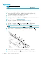
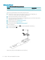
Страница 35: ...Reverse this procedure to install the heat sink Component replacement procedures 29 ...

Страница 36: ...omputer by first unplugging the power cord from the AC outlet and then unplugging the AC adapter from the computer 4 Remove the bottom cover see Bottom cover on page 22 5 Remove the battery see Battery on page 24 Remove the touchpad 1 Remove the four Phillips M2 0 2 5 screws 1 that secure the touchpad bracket to the touchpad and then remove the touchpad bracket 2 2 Release the zero insertion force...

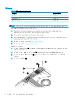
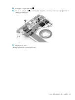
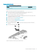
Страница 37: ...4 Remove the touchpad 3 Reverse this procedure to install the touchpad Component replacement procedures 31 ...

Страница 38: ...ery cable from the system board see Battery on page 24 Remove the display assembly 1 Disconnect the display panel cable 1 and the touch control cable 2 from the system board 2 Disconnect the WLAN antenna cables 3 from the terminals on the WLAN module NOTE The 1 white WLAN antenna cable connects to the WLAN module 1 Main terminal The 2 black WLAN antenna cable connects to the WLAN module 2 Aux term...

Страница 39: ...7 Separate the display from the computer 2 Reverse this procedure to install the display assembly Component replacement procedures 33 ...

Страница 40: ...evices connected to the computer 3 Disconnect the power from the computer by first unplugging the power cord from the AC outlet and then unplugging the AC adapter from the computer 4 Remove the bottom cover see Bottom cover on page 22 5 Remove the battery see Battery on page 24 Remove the I O board 1 Release the ZIF connector 1 to which the I O board cable is connected and then disconnect the I O ...

Страница 41: ... 6 Release the ZIF connector 2 to which the I O board cable is connected and then disconnect the I O board cable from the I O board 7 Remove the I O board Reverse this procedure to install the I O board Component replacement procedures 35 ...

Страница 42: ...l devices connected to the computer 3 Disconnect the power from the computer by first unplugging the power cord from the AC outlet and then unplugging the AC adapter from the computer 4 Remove the bottom cover see Bottom cover on page 22 5 Remove the battery see Battery on page 24 6 Remove the I O board see USB bracket I O board on page 36 Remove the USB bracket 1 Remove the Phillips M2 0 4 0 scre...

Страница 43: ...onnected to the computer 3 Disconnect the power from the computer by first unplugging the power cord from the AC outlet and then unplugging the AC adapter from the computer 4 Remove the bottom cover see Bottom cover on page 22 5 Remove the battery see Battery on page 24 6 Remove the I O board see USB bracket I O board on page 36 Remove the security cable lock bracket 1 Remove the Phillips M2 5 3 0...

Страница 44: ...low these steps 1 Shut down the computer If you are unsure whether the computer is off or in Hibernation turn the computer on and then shut it down through the operating system 2 Disconnect all external devices connected to the computer 3 Disconnect the power from the computer by first unplugging the power cord from the AC outlet and then unplugging the AC adapter from the computer 4 Remove the bo...

Страница 45: ...system board 3 until it rests at an angle NOTE The I O board cable is connected to the bottom of the system board Make sure not to accidentally damage the I O board cable when releasing the system board 5 Release the system board 4 by sliding it up and to the left at an angle as far as the I O board allows 6 Turn the system board upside down 1 Component replacement procedures 39 ...

Страница 46: ...2 to which the I O board cable is connected and then disconnect the I O board cable from the system board 8 Remove the system board Reverse this procedure to install the system board 40 Chapter 5 Removal and replacement procedures ...

Страница 47: ...ected to the computer 3 Disconnect the power from the computer by first unplugging the power cord from the AC outlet and then unplugging the AC adapter from the computer 4 Remove the bottom cover see Bottom cover on page 22 and then remove the following components a Battery see Battery on page 24 b Fan see Fan on page 27 c System board see System board on page 38 Remove the USB bracket from the sy...

Страница 48: ...evices connected to the computer 3 Disconnect the power from the computer by first unplugging the power cord from the AC outlet and then unplugging the AC adapter from the computer 4 Remove the bottom cover see Bottom cover on page 22 and then remove the following components a Battery see Battery on page 24 b Fan see Fan on page 27 c System board see System board on page 38 Remove the speakers 1 R...

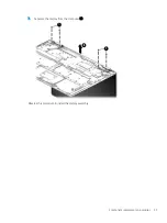
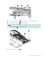
Страница 49: ...Reverse this procedure to install the speakers Component replacement procedures 43 ...

Страница 50: ...aded files If possible back up all files before resetting the computer You might want to reset the computer in the following circumstances You see the message Reset this Chrome device You are having problems with your user profile or settings You have tried restarting your computer and it s still not working properly You want to change the owner of your computer To reset your computer 1 Under the ...

Страница 51: ...ged screen displaying on your computer If this message is not already displayed Turn on the computer press and hold the esc f3 keys and then press the power button The computer restarts and the screen shows the Chrome OS is missing or damaged screen Installing the Chromebook Recovery Utility The Chromebook Recovery Utility is an app used to recover the original operating system and software progra...

Страница 52: ...uter restarts with Chrome OS reinstalled Setting up the computer after a reset or recovery After a reset or recovery is complete perform the initial setup process For details on setting up the computer go to http www support google com Erase and format the recovery media During the process of creating recovery media the USB flash drive or SD memory card is formatted for use as a recovery tool Afte...

Страница 53: ...F to 95 F Nonoperating 20 C to 60 C 4 F to 140 F Relative humidity noncondensing Operating 10 to 90 Nonoperating 5 to 95 Maximum altitude unpressurized Operating 15 m to 3 048 m 50 ft to 10 000 ft Nonoperating 15 m to 12 192 m 50 ft to 40 000 ft NOTE Applicable product safety standards specify thermal limits for plastic surfaces The device operates well within this range of temperatures 47 ...

Страница 54: ...rements are applicable to all countries and regions The length of the power cord set must be at least 1 0 m 3 3 ft and no more than 2 0 m 6 5 ft All power cord sets must be approved by an acceptable accredited agency responsible for evaluation in the country or region where the power cord set will be used The power cord sets must have a minimum current capacity of 10 A and a nominal voltage rating...

Страница 55: ...EMA 1 New Zealand SANZ 1 Norway NEMKO 1 The People s Republic of China CCC 4 Saudi Arabia SASO 7 Singapore PSB 1 South Africa SABS 1 South Korea KTL 5 Sweden SEMKO 1 Switzerland SEV 1 Taiwan BSMI 6 Thailand TISI 1 The United Kingdom ASTA 1 The United States UL 2 1 The flexible cord must be Type HO5VV F 3 conductor 0 75 mm conductor size Power cord set fittings appliance coupler and wall plug must ...

Страница 56: ...configuration 4 The flexible cord must be Type RVV 3 conductor 0 75 mm conductor size Power cord set fittings appliance coupler and wall plug must bear the CCC certification mark 5 The flexible cord must be Type H05VV F 3 conductor 0 75 mm conductor size KTL logo and individual approval number must be on each element Corset approval number and logo must be printed on a flag label 6 The flexible co...

Страница 57: ...e battery in general household waste Follow the local laws and regulations in your area for battery disposal HP encourages customers to recycle used electronic hardware HP original print cartridges and rechargeable batteries For more information about recycling programs see the HP Web site at http www hp com recycle 51 ...

Страница 58: ... headphone audio out jack 4 heat sink removal 27 28 spare part number 15 27 28 I I O board removal 34 spare part number 15 34 I O board cable spare part numbers 34 I O board cable 30P spare part number 15 I O board cable 40P spare part number 15 internal microphone 6 J jacks audio in microphone 4 audio out headphone 4 K keyboard top cover spare part numbers 14 keys esc 9 search 9 L labels Bluetoot...

Страница 59: ...ble slot 3 security product description 1 serial number computer 11 service labels locating 11 serviceability product description 2 slots microSD memory card reader 4 Speaker Kit spare part number 14 42 speakers 7 removal 42 spare part number 14 42 storage product description 1 system board removal 38 spare part numbers 14 38 T touchpad removal 30 spare part number 14 30 touchpad bracket removal 3...

Отзывы: