background image

6

Specifications

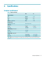
Computer specifications

Table 6-1

  Computer specifications


Metric

U.S.

Computer dimensions

Width

325.5 mm

12.8 in

Depth

218.5 mm

8.6 in

Height

17.9 mm

0.7 in

Weight (lowest configuration)

1325 g

2.9 lbs

Input power rating


Operating voltage and current

18.5 V dc @ 3.5 A – 45 W

Temperature

Operating

5°C to 35°C

41°F to 95°F

Nonoperating

–20°C to 60°C

–4°F to 140°F

Relative humidity (noncondensing)

Operating

10% to 90%

Nonoperating

5% to 95%

Maximum altitude (unpressurized)

Operating

–15 m to 3,048 m

–50 ft to 10,000 ft

Nonoperating

–15 m to 12,192 m

–50 ft to 40,000 ft

NOTE:

Applicable product safety standards specify thermal limits for plastic surfaces. The device operates well within this range of 

temperatures.

Computer specifications

43

Содержание Chromebook 14a Series

Страница 1: ...Maintenance and Service Guide HP Chromebook 14a IMPORTANT This document is intended for HP authorized service providers only ...

Страница 2: ...uting an additional warranty HP shall not be liable for technical or editorial errors or omissions contained herein First Edition February 2020 Document Part Number L93843 001 Product notice This guide describes features that are common to most models Some features may not be available on your computer To access the latest user guides go to http www hp com support and follow the instructions to fi...

Страница 3: ...ard flat surface Do not allow another hard surface such as an adjoining optional printer or a soft surface such as pillows or rugs or clothing to block airflow Also do not allow the AC adapter to contact the skin or a soft surface such as pillows or rugs or clothing during operation The device and the AC adapter comply with the user accessible surface temperature limits defined by applicable safet...

Страница 4: ...iv Safety warning notice ...

Страница 5: ...res preliminary requirements 15 Tools required 15 Service considerations 15 Plastic parts 15 Cables and connectors 15 Drive handling 16 Workstation guidelines 16 Electrostatic discharge information 16 Generating static electricity 17 Preventing electrostatic damage to equipment 17 Personal grounding methods and equipment 18 Grounding the work area 18 Recommended materials and equipment 18 Packagin...

Страница 6: ...oard 30 Power connector DC in cable 33 Display assembly 34 Keyboard with top cover 42 6 Specifications 43 Computer specifications 43 35 6 cm 14 0 in display specifications 44 7 Power cord set requirements 45 Requirements for all countries 45 Requirements for specific countries and regions 46 8 Recycling 48 Index 49 vi ...

Страница 7: ... FSB 4 MB L2 cache dual core 6 W Intel UHD 600 Graphics Graphics Internal graphics Intel UHD 605 Graphics Intel Pentium processors Intel UHD 600 Graphics Intel Celeron processors Supports HD decode DX12 and HDMI Display panel 35 6 cm 14 0 in WLED slim 3 0 mm narrow bezel 45 NTSC High definition HD 1366 768 antiglare SVA eDP 1 2 220 nits HD BrightView SVA eDP 220 nits Touch on Panel TOP Full high d...

Страница 8: ...t side Support power delivery data transfer DisplayPort 1 2 out up to 4096 2304 60 Hz and HDMI 1 4 out through adapter Media card reader Supports microSD SDHC SDXC Push push insertion and removal Keyboard pointing devices Google Keyboard Full size island style Full size island style textured backlit Touchpad requirements Multitouch gestures enabled Taps enabled as default Power requirements Batter...

Страница 9: ...y and Connects a USB device provides data transfer and for select products charges small devices when the computer is on or in Sleep mode and Connects a display device that has a USB Type C connector providing DisplayPort output NOTE Cables adapters or both purchased separately may be required 2 AC adapter and battery light White The AC adapter is connected and the battery is fully charged Amber T...

Страница 10: ...d and the battery is charging Off The battery is not charging 3 USB Type C power connector and port Connects an AC adapter that has a USB Type C connector supplying power to the computer and if needed charging the computer battery and Connects a USB device provides data transfer and for select products charges small devices when the computer is on or in Sleep mode and Connects a display device tha...

Страница 11: ...eo and record still images NOTE Camera functions vary depending on the camera hardware and software installed on your product 4 Camera light On The camera is in use The antennas are not visible from the outside of the computer For optimal transmission keep the areas immediately around the antennas free from obstructions For wireless regulatory notices see the section of the Regulatory Safety and E...

Страница 12: ...tion Component Description Touchpad zone Reads your finger gestures to move the pointer or activate items on the screen Speakers Table 2 5 Speakers and their description Component Description Speakers 2 Produce sound 6 Chapter 2 Getting to know your computer ...

Страница 13: ...computer is off press the button to turn on the computer When the computer is on press the button briefly to initiate Sleep When the computer is in the Sleep state press the button briefly to exit Sleep select products only IMPORTANT Pressing and holding down the power button results in the loss of unsaved information If the computer has stopped responding and shutdown procedures are ineffective p...

Страница 14: ...l screen mode Display apps Displays open apps NOTE Pressing this button in conjunction with ctrl takes a screenshot Brightness down Decreases the screen brightness incrementally as long as you hold down the key Press simultaneously with ctrl to decrease the keyboard backlight select products only incrementally as long as you hold down the key Brightness up Increases the screen brightness increment...

Страница 15: ...ickstand Service label Provides important information to identify your computer When contacting support you may be asked for the serial number the product number or the model number Locate this information before you contact support Table 2 8 Service label components Component 1 HP product name 2 Model number 3 Product ID 4 Serial number 5 Warranty period Regulatory label s Provide s regulatory in...

Страница 16: ...ported parts for your computer go to http partsurfer hp com select your country or region and then follow the on screen instructions NOTE Details about your computer including model serial number product key and length of warranty are on the service tag at the bottom of your computer See Labels on page 9 for details 10 Chapter 3 Illustrated parts catalog ...

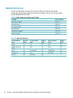
Страница 17: ...28 GB eMMC memory M03106 001 Intel Pentium Silver N5000 processor 8 GB system memory and 128 GB eMMC memory models with a backlit keyboard M03111 001 Intel Pentium Silver N5000 processor 4 GB system memory and 64 GB eMMC memory M00111 001 Intel Pentium Silver N5000 processor 4 GB system memory and 64 GB eMMC memory models with a backlit keyboard M03109 001 Intel Celeron N4020 processor 8 GB system...

Страница 18: ...Fi Bluetooth 5 0 L44796 005 10 Battery 2 cell 47 Whr L75783 005 11 Bottom cover L91523 001 12 Rubber feet L91524 001 Screw covers not illustrated L91525 001 Cables Table 3 2 Cables and their descriptions Item Component Spare part number 1 Touchpad cable L91527 001 2 Power connector cable DC in L99191 001 3 USB high speed cable L73309 001 4 USB low speed cable L73310 001 12 Chapter 3 Illustrated pa...

Страница 19: ...glare Touch on Panel TOP L91592 001 HD antiglare L91593 001 HD BrightView Touch on Panel TOP L91594 001 3 Display hinges left and right include display tape L91537 001 4 Display panel cable includes display tape For use with touch displays L91539 001 For use with nontouch displays L91538 001 5 Webcam microphone module L91540 001 6 Wireless antennas dual includes display tape L91533 001 7 Webcam ca...

Страница 20: ...adapter USB Type C 45 W nPFC 3 pin 1 8 m L43407 001 Screw Kit L91542 001 Screw protective tape L91525 001 Power adapter for use in Japan C5 226768 001 Power cord C5 1 0 m For use in Australia L19358 001 For use in Denmark L19360 001 For use in Europe L19361 001 For use in India L19363 001 For use in Japan L19365 001 For use in North America L19367 001 For use in South Korea L19366 001 For use in T...

Страница 21: ...parts IMPORTANT Using excessive force during disassembly and reassembly can damage plastic parts Cables and connectors IMPORTANT When servicing the computer be sure that cables are placed in their proper locations during the reassembly process Improper cable placement can damage the computer Cables must be handled with extreme care to avoid damage Apply only the tension required to unseat or seat ...

Страница 22: ...ith approved static shielding material Use a wrist strap connected to a properly grounded work surface and use properly grounded tools and equipment Use conductive field service tools such as cutters screw drivers and vacuums When fixtures must directly contact dissipative surfaces use fixtures made only of static safe materials Keep the work area free of nonconductive materials such as ordinary p...

Страница 23: ... 6 000 V 2 000 V Removing DIPs from vinyl tray Removing DIPs from polystyrene foam Removing bubble pack from PCB Packing PCBs in foam lined box 2 000 V 3 500 V 7 000 V 5 000 V 4 000 V 5 000 V 20 000 V 11 000 V 11 500 V 14 500 V 26 500 V 21 000 V Electronic components can be packaged together in plastic tubes trays or polystyrene foam NOTE As little as 700 V can degrade a product Preventing electro...

Страница 24: ...prevent static damage at the work area take the following precautions Cover the work surface with approved static dissipative material Provide a wrist strap connected to the work surface and properly grounded tools and equipment Use static dissipative mats foot straps or air ionizers to give added protection Handle electrostatic sensitive components parts and assemblies by the case or PCB laminate...

Страница 25: ...D sensitive parts and assemblies with conductive or approved containers or packaging Keep ESD sensitive parts in their containers until the parts arrive at static free workstations Place items on a grounded surface before removing items from their containers Always be properly grounded when touching a component or assembly Store reusable ESD sensitive parts from assemblies in protective packaging ...

Страница 26: ...dures There are as many as 45 screws that must be removed replaced and or loosened when servicing the computer Make special note of each screw size and location during removal and replacement Preparation for disassembly See Removal and replacement procedures preliminary requirements on page 15 for initial safety procedures 1 Turn off the computer If you are unsure whether the computer is off or in...

Страница 27: ...y Preparation for disassembly on page 20 Remove the bottom cover 1 Peel the two rubber strips 1 and remove the two screw covers 2 from the bottom cover 1 2 Remove the eight Phillips M2 0 5 0 screws 3 from the bottom cover 3 Insert a nonmarking nonconductive tool between the bottom cover and the computer chassis 1 and then flex and lift the bottom cover enough to separate it from the computer Compo...

Страница 28: ...4 Remove the bottom cover from the computer 2 Reverse this procedure to install the bottom cover 22 Chapter 5 Removal and replacement procedures for authorized service provider parts ...

Страница 29: ...tom cover see Bottom cover on page 21 Remove the battery 1 Lift the tape from the top of the battery connector 1 and then the disconnect battery cable from the system board 2 2 Remove the speaker cable from the routing along the bottom of the battery 3 3 Remove the four Phillips M2 0 3 5 screws 4 that secure the battery to the computer 4 Remove the battery from the computer 5 Reverse this procedur...

Страница 30: ... follow these steps 1 Prepare the computer for disassembly Preparation for disassembly on page 20 2 Remove the bottom cover see Bottom cover on page 21 3 Disconnect the battery see Battery on page 23 Remove the WLAN module 1 Disconnect the WLAN antenna cables 1 from the terminals on the WLAN module NOTE The WLAN antenna cable labeled 1 connects to the WLAN module Main terminal labeled 1 The WLAN a...

Страница 31: ... connected to the terminal on the WLAN module a protective sleeve must be installed on the antenna connector as shown in the following illustration Reverse this procedure to install the WLAN module Component replacement procedures 25 ...

Страница 32: ...ottom cover on page 21 3 Disconnect the battery see Battery on page 23 Remove the speaker 1 Disconnect the speaker cable from the system board 1 2 Remove the four Phillips M2 0 4 8 screws 2 that secure the speakers to the computer 3 Remove the speakers 3 while removing the cable from the routing along the bottom of the battery Reverse this procedure to install the speakers 26 Chapter 5 Removal and...

Страница 33: ... Prepare the computer for disassembly Preparation for disassembly on page 20 2 Remove the bottom cover see Bottom cover on page 21 3 Remove the battery see Battery on page 23 Remove the touchpad 1 Remove the three Phillips M2 0 2 0 screws 1 that secure the touchpad bracket to the computer and then remove the bracket 2 2 Disconnect the cable from the ZIF connector on the touchpad board 1 3 Lift the...

Страница 34: ...ips M2 0 2 0 screws 3 that secure the touchpad to the computer and then remove the touchpad 4 Reverse this procedure to install the touchpad 28 Chapter 5 Removal and replacement procedures for authorized service provider parts ...

Страница 35: ...se steps 1 Prepare the computer for disassembly Preparation for disassembly on page 20 2 Remove the bottom cover see Bottom cover on page 21 3 Disconnect the battery see Battery on page 23 Remove the USB board 1 Disconnect the top cable from the USB board 1 2 Disconnect the two flat ribbon cables from the two reverse ZIF connectors on the USB board 2 3 Remove the four Phillips M2 0 3 5 screws 3 th...

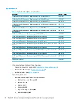
Страница 36: ...tel Celeron N4000 processor 8 GB system memory and 128 GB eMMC memory M03105 001 Intel Celeron N4000 processor 8 GB system memory and 128 GB eMMC memory models with a backlit keyboard M03110 001 Intel Celeron N4000 processor 4 GB system memory and 64 GB eMMC memory M00110 001 Intel Celeron N4000 processor 4 GB system memory and 64 GB eMMC memory models with a backlit keyboard M03108 001 Intel Cele...

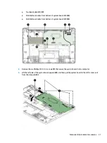
Страница 37: ...d cable from bottom of system board ZIF 9 2 Remove the six Phillips M2 0 3 5 screws 1 that secure the system board to the computer 3 Lift the left side of the system board upward 2 and then pull the system board to the left to remove it from the computer 3 Component replacement procedures 31 ...

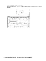
Страница 38: ...stall the system board When replacing the system board be sure to replace the thermal pad in the location as shown in the following illustration 32 Chapter 5 Removal and replacement procedures for authorized service provider parts ...

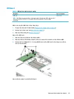
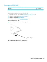
Страница 39: ...Prepare the computer for disassembly Preparation for disassembly on page 20 2 Remove the bottom cover see Bottom cover on page 21 3 Remove the battery see Battery on page 23 4 Remove the system board see System board on page 30 Remove the power connector cable Disconnect the power connector cable from the system board Reverse this procedure to install the power connector cable Component replacemen...

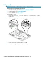
Страница 40: ... 21 3 Disconnect the battery see Battery on page 23 Remove the display assembly 1 Disconnect the wireless antenna cables from the WLAN module and remove the cable from the clips in the computer 2 2 Disconnect the display cable 3 and the webcam cable 4 from the system board 3 Open the display until the hinges are in the open position 1 4 Remove the four Phillips M2 5 5 5 screws 2 from the hinges 34...

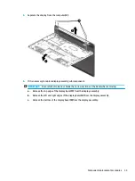
Страница 41: ...not to bend or break the narrow sections of the bezel when removing a Release the top edge of the display bezel 1 from the display assembly b Release the left and right edges of the display bezel 2 from the display assembly c Release the bottom of the display bezel 3 from the display assembly Component replacement procedures 35 ...

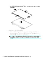
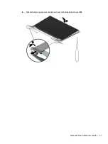
Страница 42: ...p the tape and then roll the tape around the tweezers 1 as you pull the tape from behind the panel 2 Use the same procedure to remove both pieces of tape You have to pull on the tape multiple times before it is completely removed TIP Rolling the tape around the tweezers or the shaft of a screwdriver as you pull it can help to avoid pulling too hard and tearing the tape To avoid tearing the tape pu...

Страница 43: ...b Rotate the display panel over and place it next to the display back cover 3 Component replacement procedures 37 ...

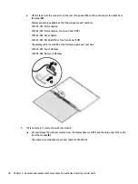
Страница 44: ...L91594 001 HD BrightView Touch on Panel TOP The display cable is available as the following spare part numbers L91539 001 Touch displays L91538 001 Nontouch displays 8 If it is necessary to remove the webcam module Lift and release the webcam module from the display back cover 1 and then disconnect the cable from the module 2 The webcam is available as spare part number L91540 001 38 Chapter 5 Rem...

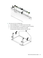
Страница 45: ... 0 2 5 screw 1 from the top of each hinge b Remove the three Phillips M2 5 2 5 screws 2 from the bottom of each hinge c Remove the display hinges from the display back cover 3 The display hinges are available as spare part number L91537 001 Component replacement procedures 39 ...

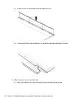
Страница 46: ...following illustration to determine proper cable routing around the hinge 10 If it is necessary to remove the webcam cable a Remove the cable from its routing path along the bottom of the display back cover 1 40 Chapter 5 Removal and replacement procedures for authorized service provider parts ...

Страница 47: ...ove the antenna cables from the channels on the sides and bottom of the display back cover 2 and then remove the antennas and cables 3 The wireless antennas are available as spare part number L91533 001 The display back cover is available as the following spare part numbers L91530 001 Mineral silver L91529 001 Forest teal L91531 001 Ceramic white Reverse these procedures to reassemble and install ...

Страница 48: ...Ash silver no backlight L91511 xx1 Ash silver backlit L91512 xx1 Natural silver no backlight L91513 xx1 Natural silver backlit L91514 xx1 Table 5 10 Keyboard country codes For use in country or region Spare part number For use in country or region Spare part number For use in country or region Spare part number Belgium A41 Italy 061 Spain 071 Denmark Finland and Norway DH1 Japan 291 Taiwan AB1 Fra...

Страница 49: ... V dc 3 5 A 45 W Temperature Operating 5 C to 35 C 41 F to 95 F Nonoperating 20 C to 60 C 4 F to 140 F Relative humidity noncondensing Operating 10 to 90 Nonoperating 5 to 95 Maximum altitude unpressurized Operating 15 m to 3 048 m 50 ft to 10 000 ft Nonoperating 15 m to 12 192 m 50 ft to 40 000 ft NOTE Applicable product safety standards specify thermal limits for plastic surfaces The device oper...

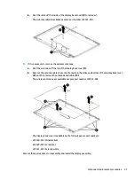
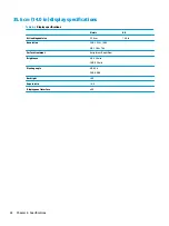
Страница 50: ...ric U S Active diagonal size 35 6 cm 14 0 in Resolution FHD 1920 1080 HD 1366 768 Surface treatment Antiglare or BrightView Brightness HD 220 nits FHD 250 nits Viewing angle HD SVA FHD UWVA Backlight LED Aspect ratio 16 9 Display panel interface eDP 44 Chapter 6 Specifications ...

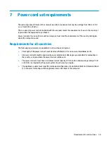
Страница 51: ...equirements are applicable to all countries and regions The length of the power cord set must be at least 1 0 m 3 3 ft and no more than 2 0 m 6 5 ft All power cord sets must be approved by an acceptable accredited agency responsible for evaluation in the country or region where the power cord set will be used The power cord sets must have a minimum current capacity of 10 A and a nominal voltage ra...

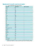
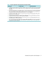
Страница 52: ...JIS 3 The Netherlands KEMA 1 New Zealand SANZ 1 Norway NEMKO 1 The People s Republic of China CCC 4 Saudi Arabia SASO 7 Singapore PSB 1 South Africa SABS 1 South Korea KTL 5 Sweden SEMKO 1 Switzerland SEV 1 Taiwan BSMI 6 Thailand TISI 1 The United Kingdom ASTA 1 The United States UL 2 1 The flexible cord must be Type HO5VV F 3 conductor 0 75 mm conductor size Power cord set fittings appliance coup...

Страница 53: ...303 7 A 125 V ac configuration 4 The flexible cord must be Type RVV 3 conductor 0 75 mm conductor size Power cord set fittings appliance coupler and wall plug must bear the CCC certification mark 5 The flexible cord must be Type H05VV F 3 conductor 0 75 mm conductor size KTL logo and individual approval number must be on each element Approval number and logo must be printed on a flag label 6 The f...

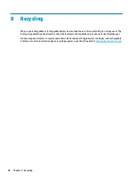
Страница 54: ...in general household waste Follow the local laws and regulations in your area for battery disposal HP encourages customers to recycle used electronic hardware HP original print cartridges and rechargeable batteries For more information about recycling programs see the HP website at http www hp com recycle 48 Chapter 8 Recycling ...

Страница 55: ...ecifications 43 connectors power 3 4 D display assembly removal 34 display back cover spare part number 41 display components 5 display panel product description 1 removal 36 spare part numbers 13 display panel cable spare part numbers 13 38 display specifications 44 E electrostatic discharge ESD 16 preventing damage 17 esc key identifying 7 F forward action key 8 full screen action key 8 G graphi...

Страница 56: ...Kit spare part number 14 security product description 2 serial number computer 9 service labels locating 9 serviceability product description 2 slots microSD memory card reader 4 speaker removal 26 spare part numbers 26 speakers identifying 6 spare part number 11 special keys using 7 specifications computer 43 display 44 static electricity 17 storage product description 1 system board removal 30 s...

Отзывы: