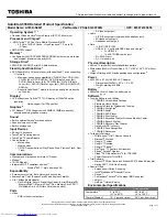
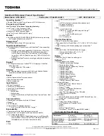
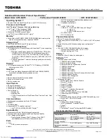
background image

System board

NOTE:

The system board is equipped with an Nvidia CD570M 2.10-GHz quad core processor and a graphics

subsystem with UMA memory and includes replacement thermal material.

Description

Spare part number

Equipped with 4.0-GB of system memory and 32-GB of eMMC primary storage for use only on computer
models not equipped with WWAN capability for use on all computer models

787727-001

Equipped with 4.0-GB of system memory and 16-GB of eMMC primary storage for use only on computer
models not equipped with WWAN capability for use on all computer models

787726-001

Equipped with 2.0-GB of system memory and 32-GB of eMMC primary storage for use only on computer
models not equipped with WWAN capability for use on all computer models

787725-001

Equipped with 2.0-GB of system memory and 16-GB of eMMC primary storage for use only on computer
models not equipped with WWAN capability for use on all computer models

787724-001

Before removing the system board, follow these steps:

1.

Turn off the computer. If you are unsure whether the computer is off or in Hibernation, turn the
computer on, and then shut it down through the operating system.

2.

Disconnect the power from the computer by unplugging the power cord from the computer.

3.

Disconnect all external devices from the computer.

4.

Remove the keyboard/top cover (see 

Keyboard/top cover on page 25

).

Remove the system board:

1.

Disconnect the speaker cable 

(1)

 from the system board.

2.

Release the ZIF connector 

(2)

 to which the display panel cable is attached, and then disconnect the

display panel cable from the system board.

3.

Disconnect the WLAN antenna cables 

(3)

 from the WLAN terminals on the system board.

NOTE:

The white WLAN antenna cable labeled “1/Main” connects to the system board “Main” terminal.

The black WLAN antenna cable labeled “2/Aux” connects to the system board “Aux” terminal.

4.

Disconnect the power connector cable 

(4)

 from the system board.

Component replacement procedures

35

Содержание Chromebook 14-X0 SERIES

Страница 1: ...HP Chromebook model numbers 14 x000 through 14 x099 Maintenance and Service Guide IMPORTANT This document is intended for HP authorized service providers only ...

Страница 2: ...n the express warranty statements accompanying such products and services Nothing herein should be construed as constituting an additional warranty HP shall not be liable for technical or editorial errors or omissions contained herein First Edition November 2014 Document Part Number 780442 002 Product notice This guide describes features that are common to most models Some features may not be avai...

Страница 3: ...w another hard surface such as an adjoining optional printer or a soft surface such as pillows or rugs or clothing to block airflow Also do not allow the AC adapter to contact the skin or a soft surface such as pillows or rugs or clothing during operation The device and the AC adapter comply with the user accessible surface temperature limits defined by the International Standard for Safety of Inf...

Страница 4: ...iv Safety warning notice ...

Страница 5: ...ts 11 Miscellaneous parts 12 Sequential part number listing 14 4 Removal and replacement preliminary requirements 20 Tools required 20 Service considerations 20 Plastic parts 20 Cables and connectors 21 Drive handling 21 Grounding guidelines 21 Electrostatic discharge damage 21 Packaging and transporting guidelines 23 Workstation guidelines 23 5 Removal and replacement procedures 25 Component repl...

Страница 6: ...d set requirements 51 Requirements for all countries 51 Requirements for specific countries and regions 51 8 Statement of memory volatility 53 Nonvolatile memory usage 55 Questions and answers 57 Using HP Sure Start select models only 58 9 Recycling 59 Index 60 vi ...

Страница 7: ...VA 200 nits typical brightness 14 0 in FHD WLED Antiglare 1920x1080 slim 3 0mm SVA 300 nits eDP non Touch non WWAN smoke silver ID only 14 0 in HD WLED AntiGlare 1366x768 flat 3 6mm SVA 220 nits eDP non Touch only bridge 220 nits into SA of 200 nits Touch solution with bezel multitouch enabled Memory Supports DDR3L 1600MHz Supports up to 4096 MB maximum on board system memory 4 pieces of 256 MB 16...

Страница 8: ... microphone audio out stereo headphone combo jack HDMI v1 4 supporting up to 1920 1080 60Hz Ports continued RJ 45 Ethernet USB one USB 3 0 port 2 USB 2 0 ports For use on all computer models Keyboard pointing devices Full sized textured island style Google keyboard Jack black for use only on HP Chromebook 14 G3 Full sized textured island style Google keyboard white for use only on HP Chromebook 14...

Страница 9: ...em Description 1 WWAN antennas 2 5 WLAN antennas 2 2 Internal microphone 6 Power button 3 HP TrueVision HD Webcam 7 TouchPad 4 Webcam light The position of the WLAN antennas differs depending on model Antennas are not visible on the exterior of the device Display 3 ...

Страница 10: ...ard reader 2 USB port 5 Power light 3 Audio out headphone Audio in microphone jack Right side Item Description Item Description 1 SIM card reader 3 AC adapter Battery light 2 USB port 4 Power connector select models only 4 Chapter 2 External component identification ...

Страница 11: ...r hp com select your country or region and then follow the on screen instructions Locating the service tag information The product name 1 serial number 2 product number 3 warranty information 4 and model number 5 are located on the bottom of the computer This information may be needed when travelling internationally or contacting support Locating the service tag information 5 ...

Страница 12: ...Computer major components 6 Chapter 3 Illustrated parts catalog ...

Страница 13: ... for use only on HP Chromebook 14 PC 787734 031 For use in the United States for use only on HP Chromebook 14 PC 787734 001 In ocean turquoise finish For use in Belgium for use only on HP Chromebook 14 PC 787732 A41 For use in Canada for use only on HP Chromebook 14 PC 787732 DB1 For use in Denmark Finland and Norway for use only on HP Chromebook 14 PC 787732 DH1 For use in France for use only on ...

Страница 14: ...Chromebook 14 PC 787733 061 For use in the Netherlands for use only on HP Chromebook 14 PC 787733 B31 For use in Russia for use only on HP Chromebook 14 PC 787733 251 For use in Spain for use only on HP Chromebook 14 PC 787733 071 For use in Switzerland for use only on HP Chromebook 14 PC 787733 BG1 For use in the United Kingdom and Singapore for use only on HP Chromebook 14 PC 787733 031 For use ...

Страница 15: ... on all computer models 787726 001 Equipped with 2 0 GB of system memory and 32 GB of eMMC primary storage for use only on computer models not equipped with WWAN capability for use on all computer models 787725 001 Equipped with 2 0 GB of system memory and 16 GB of eMMC primary storage for use only on computer models equipped with WWAN capability for use on HP Chromebook 14 PC and for use on HP Ch...

Страница 16: ... 14 G3 not illustrated includes 2 display bezel screw covers 4 rubber feet and 3 rubber screw covers 788510 001 Display assembly subcomponents TouchScreen display assembly components Item Description Spare part number 1 Display panel assembly 14 0 in BrightView 1920 1080 FHD WLED slim 3 0 mm SVA includes bezel display panel cable and TouchScreen cable In neon green finish for use only on HP Chrome...

Страница 17: ...Description Spare part number 1 Display bezel In neon green finish for use only on HP Chromebook 14 PC 787707 001 In ocean turquoise finish for use only on HP Chromebook 14 PC 787705 001 In smoke silver finish for use only on HP Chromebook 14 PC 787708 001 In sorbet orange finish for use only on HP Chromebook 14 PC 787706 001 In smoke silver for use only on HP Chromebook 14 PC 787708 001 Jack blac...

Страница 18: ...90 001 In Jack black non TouchScreen for use only on HP Chromebook 14 G3 788505 001 In Jack black TouchScreen for use only on HP Chromebook 14 G3 788506 001 In Jack black for use only on HP Chromebook 14 G3 788503 001 In Jack black for use only on HP Chromebook 14 G3 WWAN 788504 001 Miscellaneous parts Component Spare part number AC adapter 65 W HP Smart AC adapter non PFC EM 4 5 mm for use on all...

Страница 19: ...display bezel screw covers 4 rubber feet and 2 rubber screw covers 787721 001 Rubber Kit for use only on HP Chromebook 14 G3 includes 2 display bezel screw covers 4 rubber feet and 2 rubber screw covers 788510 001 Screw Kit for use on all computer models 787722 001 Miscellaneous parts 13 ...

Страница 20: ...es and transceivers for use only on HP Chromebook 14 PC 787691 001 Display enclosure in neon green finish for use only on computer models equipped with a non TouchScreen display includes wireless antenna cables and transceivers for use only on HP Chromebook 14 PC 787692 001 Display enclosure in smoke silver finish for use only on computer models equipped with a non TouchScreen display includes wir...

Страница 21: ...ly on computer models equipped with a TouchScreen display includes TouchScreen cable and webcamera microphone module cable for use on HP Chromebook 14 PC and for use on HP Chromebook 14 G3 787711 001 Heat sink includes grounding tape and replacement thermal material for use on all computer models 787712 001 Display Hinge Kit for use only on computer models equipped with a non TouchScreen display f...

Страница 22: ...WAN capability includes replacement thermal material for use on all computer models 787732 001 Keyboard top cover in ocean turquoise finish for use in the United States includes keyboard cable for use only on HP Chromebook 14 PC 787732 031 Keyboard top cover in ocean turquoise finish for use in the United Kingdom and Singapore includes keyboard cable for use only on HP Chromebook 14 PC 787732 041 ...

Страница 23: ...use in Canada includes keyboard cable for use only on HP Chromebook 14 PC 787733 DH1 Keyboard top cover in neon green finish for use in Denmark Finland and Norway includes keyboard cable for use only on HP Chromebook 14 PC 787734 001 Keyboard top cover in sorbet orange finish for use in the United States includes keyboard cable for use only on HP Chromebook 14 PC 787734 031 Keyboard top cover in s...

Страница 24: ... the Netherlands includes keyboard cable for use only on HP Chromebook 14 PC 787735 BG1 Keyboard top cover in smoke silver finish for use in Switzerland includes keyboard cable for use only on HP Chromebook 14 PC 787735 DB1 Keyboard top cover in smoke silver finish for use in Canada includes keyboard cable for use only on HP Chromebook 14 PC 787735 DH1 Keyboard top cover in smoke silver finish for...

Страница 25: ...ish for use in Japan for use only on HP Chromebook 14 G3 788511 A41 Keyboard top cover in Jack black finish for use in Belgium for use only on HP Chromebook 14 G3 788511 B31 Keyboard top cover in Jack black finish for use in the Netherland for use only on HP Chromebook 14 G3 788511 BG1 Keyboard top cover in Jack black finish for use in Switzerland for use only on HP Chromebook 14 G3 788511 DH1 Key...

Страница 26: ...ons that you must keep in mind during disassembly and assembly procedures NOTE As you remove each subassembly from the computer place the subassembly and all accompanying screws away from the work area to prevent damage Plastic parts CAUTION Using excessive force during disassembly and reassembly can damage plastic parts Use care when handling the plastic parts Apply pressure only at the points de...

Страница 27: ...al drive be sure that a diskette or disc is not in the drive and be sure that the optical drive tray is closed Handle drives on surfaces covered with at least one inch of shock proof foam Avoid dropping drives from any height onto any surface After removing drive place it in a static proof bag Avoid exposing a drive to products that have magnetic fields such as monitors or speakers Avoid exposing ...

Страница 28: ...ng table shows how humidity affects the electrostatic voltage levels generated by different activities CAUTION A product can be degraded by as little as 700 V Typical electrostatic voltage levels Relative humidity Event 10 40 55 Walking across carpet 35 000 V 15 000 V 7 500 V Walking across vinyl floor 12 000 V 5 000 V 3 000 V Motions of bench worker 6 000 V 800 V 400 V Removing DIPS from plastic ...

Страница 29: ... to ground and that proper materials are selected to avoid static charging When grounding is not possible use an ionizer to dissipate electric charges Workstation guidelines Follow these grounding workstation guidelines Cover the workstation with approved static shielding material Use a wrist strap connected to a properly grounded work surface and use properly grounded tools and equipment Use cond...

Страница 30: ... the operator and ground To be effective the conductive must be worn in contact with the skin The following grounding equipment is recommended to prevent electrostatic damage Antistatic tape Antistatic smocks aprons and sleeve protectors Conductive bins and other assembly or soldering aids Nonconductive foam Conductive computerop workstations with ground cords of one megohm resistance Static dissi...

Страница 31: ...Netherlands 787734 B31 For use in Canada 787734 DB1 For use in Russia 787734 251 For use in Denmark Finland and Norway 787734 DH1 For use in Spain 787734 071 For use in France 787734 051 For use in Switzerland 787734 BG1 For use in Germany 787734 041 For use in the United Kingdom and Singapore 787734 031 For use in Italy 787734 061 For use in the United States 787734 001 Keyboard top cover in ocea...

Страница 32: ... B31 For use in Canada 788511 DB1 For use in Russia 788511 251 For use in Denmark Finland and Norway 788511 DH1 For use in Spain 788511 071 For use in France 788511 051 For use in Switzerland 788511 BG1 For use in Germany 788511 041 For use in the United Kingdom and Singapore 788511 031 For use in Italy 788511 061 For use in the United States 788511 001 For use in Latin America 788511 161 For use ...

Страница 33: ...losure 7 Turn the computer right side up with the front toward you 8 Open the computer as far as it will open 9 Lift the front edge 1 of the keyboard top cover until it separates from the front edge of the base enclosure 10 Lift the left 2 and right sides of the keyboard top cover until they separate from the left and right sides of the base enclosure 11 Disconnect the battery cable 3 from the sys...

Страница 34: ...TouchPad cable is attached and then disconnect the TouchPadd cable from the system board 14 Remove keyboard top cover 6 by sliding it forward Reverse this procedure to install the keyboard top cover 28 Chapter 5 Removal and replacement procedures ...

Страница 35: ... cover see Keyboard top cover on page 25 Remove the TouchPad button board 1 Turn the keyboard top cover upside down with the front toward you 2 Detach the TouchPad cable 1 from the keyboard top cover The TouchPad cable is attached to the keyboard top cover with double sided adhesive 3 Remove the two Phillips PM1 9 2 4 broad head screws 2 that secure the TouchPad to the keyboard top cover 4 Detach ...

Страница 36: ...puter is off or in Hibernation turn the computer on and then shut it down through the operating system 2 Disconnect all external devices connected to the computer 3 Disconnect the power from the computer by first unplugging the power cord from the AC outlet and then unplugging the AC adapter from the computer 4 Remove the keyboard top cover see Keyboard top cover on page 25 Remove the WWAN module ...

Страница 37: ...an angle NOTE If the WWAN antenna is not connected to the terminal on the WWAN module a protective sleeve must be installed on the antenna connector as shown in the following illustration Reverse this procedure to install the WWAN module Component replacement procedures 31 ...

Страница 38: ...rd from the computer 3 Disconnect all external devices from the computer 4 Remove the keyboard top cover see Keyboard top cover on page 25 Remove the battery 1 Remove the eight Phillips PM1 9 2 8 screws 1 that secure the battery to the base enclosure 2 Detach the connector board cable 2 from the battery The connector board cable is attached to the battery with double sided adhesive 3 Lift the fron...

Страница 39: ...s off or in Hibernation turn the computer on and then shut it down through the operating system 2 Disconnect the power from the computer by unplugging the power cord from the computer 3 Disconnect all external devices from the computer 4 Remove the keyboard top cover see Keyboard top cover on page 25 Remove the connector board 1 Release the ZIF connector 1 to which the connector board ribbon cable...

Страница 40: ...4 Remove the connector board 4 and cable Reverse this procedure to install the connector board 34 Chapter 5 Removal and replacement procedures ...

Страница 41: ...pped with WWAN capability for use on all computer models 787724 001 Before removing the system board follow these steps 1 Turn off the computer If you are unsure whether the computer is off or in Hibernation turn the computer on and then shut it down through the operating system 2 Disconnect the power from the computer by unplugging the power cord from the computer 3 Disconnect all external device...

Страница 42: ...emove the four Philllips PM1 9 2 4 broad head screws 1 that secure the system board to the base enclosure 7 Lift the right side of the system board 2 until it rests at an angle 8 Remove the system board 3 by sliding it up and to the right at an angle Reverse this procedure to install the system board 36 Chapter 5 Removal and replacement procedures ...

Страница 43: ...own through the operating system 2 Disconnect the power from the computer by unplugging the power cord from the computer 3 Disconnect all external devices from the computer 4 Remove the keyboard top cover see Keyboard top cover on page 25 5 Remove the system board see System board on page 35 Remove the heat sink 1 Detach the two pieces of ground tape 1 that secure the heat sink to the system board...

Страница 44: ...om the surfaces of the system board and the heat sink components each time the heat sink is removed Thermal paste is used on the processor 1 and the heat sink section 2 that services it Reverse this procedure to install the heat sink 38 Chapter 5 Removal and replacement procedures ...

Страница 45: ...system 2 Disconnect the power from the computer by unplugging the power cord from the computer 3 Disconnect all external devices from the computer 4 Remove the keyboard top cover see Keyboard top cover on page 25 5 Remove the battery see Battery on page 32 Remove the speakers 1 Disconnect the speaker cable 1 from the system board 2 Release the speaker cables from the routing clips 2 and channels b...

Страница 46: ...te WLAN antenna cable labeled 1 Main connects to the system board Main terminal The black WLAN antenna cable labeled 2 Aux connects to the system board Aux terminal The red WWAN antenna cable labeled 5 Main connects to the WWAN module Main terminal The blue WWAN antenna cable labeled 6 Aux connects to the WWAN module Aux terminal 3 Release the wireless antenna cables from the routing clips 3 built...

Страница 47: ...anel c Turn the display assembly upside down with the top edge toward you d Use a case utility tool 1 or similar flat plastic tool to separate the display enclosure from the display panel assembly e Lift the top edge of the display enclosure 2 until it separates from the display panel assembly f Swing the top edge of the display enclosure 1 up and back until it rests upside down behind the display...

Страница 48: ...oke silver finish for use only on HP Chromebook 14 PC 787689 001 For use on non TouchScreen computer models in ocean turquoise finish for use only on HP Chromebook 14 PC 787690 001 For use on non TouchScreen computer models in sorbet orange for use only on HP Chromebook 14 PC 788505 001 For use on non TouchScreen computer models in Jack black finish for use only on HP Chromebook 14 G3 788506 001 F...

Страница 49: ...rews that secure the display hinges 3 Two Phillips PM2 4 3 6 screws that secure the display hinges c Remove the display hinges and display hinge support brackets 4 The TouchScreen display assembly display hinges are included in the Display Hinge Kit spare part number 787712 001 for use on all computer models 9 If it is necessary to replace the display panel cable a Disconnect the display panel cab...

Страница 50: ... on HP Chromebook 14 G3 b Remove the two Phillips PM2 0 2 2 broad head screws 2 that secure the display panel to the display enclosure c Flex the inside edges of the bottom edge 3 the left and right sides 4 and the bottom edge 5 of the display bezel until the bezel disengages from the display enclosure d Remove the display bezel 6 The non TouchScreen display assembly display bezel is available usi...

Страница 51: ...tached to the display enclosure with double sided adhesive at two locations c Disconnect the webcam microphone module cable 2 from the webcam microphone module d Remove the webcam microphone module The webcam microphone module is available using spare part number 787736 001 for use on all computer models 12 If it is necessary to replace the display panel Component replacement procedures 45 ...

Страница 52: ... panel f Remove the display panel 3 The non TouchScreen display assembly display panel is available using the following spare part numbers 787719 001 For use on computer models in ocean turquoise finish for use only on HP Chromebook 14 PC 787717 001 For use on computer models in ocean turquoise finish for use only on HP Chromebook 14 PC 787720 001 For use on computer models in ocean turquoise fini...

Страница 53: ... that secure the display hinges and display hinge support brackets to the display enclosure 1 Two Phillips PM1 9 2 9 screws that secure the display hinge brackets 2 Four Phillips PM2 4 3 1 broad head screws that secure the display hinges 3 Two Phillips PM2 4 3 6 screws that secure the display hinges Component replacement procedures 47 ...

Страница 54: ...14 If it is necessary to replace the display panel cable a Disconnect the display panel cable from the webcam microphone module b Remove the display panel c Remove the display hinges and brackets d Release the display panel cable from the retention clips 1 and channel built into the top left and bottom edges of the display enclosure 48 Chapter 5 Removal and replacement procedures ...

Страница 55: ...y assembly display panel cable is available using spare part number 787709 001 for use on all computer models and includes the webcam microphone module cable Reverse this procedure to reassemble and install the display assembly Component replacement procedures 49 ...

Страница 56: ...ice operating voltage and current can be found on the system regulatory label Temperature Operating 5 C to 35 C 41 F to 95 F Nonoperating 20 C to 60 C 4 F to 140 F Relative humidity noncondensing Operating 10 to 90 Nonoperating 5 to 95 Maximum altitude unpressurized Operating 15 m to 3 048 m 50 ft to 10 000 ft Nonoperating 15 m to 12 192 m 50 ft to 40 000 ft NOTE Applicable product safety standard...

Страница 57: ...approved by an acceptable accredited agency responsible for evaluation in the country or region where the power cord set will be used The power cord sets must have a minimum current capacity of 10 amps and a nominal voltage rating of 125 or 250 V AC as required by the power system of each country or region The appliance coupler must meet the mechanical configuration of an EN 60 320 IEC 320 Standar...

Страница 58: ...ble cord and wall plug must bear a T mark and registration number in accordance with the Japanese Dentori Law The flexible cord must be Type VCT or VCTF 3 conductor 1 00 mm conductor size The wall plug must be a two pole grounding type with a Japanese Industrial Standard C8303 7 A 125 V configuration 4 The flexible cord must be Type RVV 3 conductor 0 75 mm conductor size Power cord set fittings ap...

Страница 59: ...rogramming nonvolatile memory that does not store personal data is neither necessary nor recommended a ERROR Target for reference type variable varref ID was not found ERROR NOTE If the system has a BIOS administrator password enter the password at the prompt b Select Main select Restore Defaults and then select Yes to load defaults c Select the Security menu select Restore Security Level Defaults...

Страница 60: ...ROR b Select the Security menu and scroll down to the Utilities menu c Select Hard Drive Tools d Under Utilities select Secure Erase select the hard drive storing the data you want to clear and then follow the on screen instructions to continue or Clear the contents of the drive by using the following Disk Sanitizer command steps IMPORTANT If you clear data using Disk Sanitizer it cannot be recove...

Страница 61: ...KBytes not customer accessible No Yes Stores NIC configuration and NIC firmware NIC EEPROM is programmed using a utility from the NIC vendor that can be run from DOS A utility is required to write data to this memory and is available from the NIC vendor Writing data to this ROM in an inappropriate manner will render the NIC non functional DIMM Serial Presence Detect SPD configuration data 256 Byte...

Страница 62: ...dates digitally signed by Intel can be applied using this utility Bluetooth flash 2 Mbit No Yes Stores Bluetooth configuration and firmware Bluetooth flash is programmed at the factory Tools for writing data to this memory are not publicly available but can be obtained from the silicon vendor A utility is required for writing data to this memory and is made available through newer versions of the ...

Страница 63: ... provides functionality beyond that of the legacy BIOS In addition the UEFI BIOS works to initialize the computer s hardware before loading and executing the OS the run time environment allows the loading and execution of software programs from storage devices to provide more functionality such as advanced hardware diagnostics with the ability to display more detailed system information and advanc...

Страница 64: ...ERROR Target for reference type variable varref ID was not found ERROR b Select the Security menu select Secure Boot Configuration and then follow the on screen instructions c At the Secure Boot Configuration window select Secure Boot select Clear Secure Boot Keys and then follow the on screen instructions to continue Using HP Sure Start select models only Select computer models are configured wit...

Страница 65: ...e battery in general household waste Follow the local laws and regulations in your area for battery disposal HP encourages customers to recycle used electronic hardware HP original print cartridges and rechargeable batteries For more information about recycling programs see the HP Web site at http www hp com recycle 59 ...

Страница 66: ...e part numbers 11 18 19 46 display panel assembly spare part numbers 10 display panel cable removal 43 48 spare part numbers 11 12 15 44 49 drives precautions 21 preventing damage 21 E electrostatic discharge 21 equipment guidelines 24 external media cards product description 2 F feet removal 27 spare part number 27 G graphics product description 1 grounding guidelines 21 guidelines equipment 24 g...

Страница 67: ... 18 27 Rubber Kit spare part numbers 13 S screw covers removal 27 spare part number 27 Screw Kit spare part number 13 16 sensors product description 1 service considerations cables 21 connectors 21 plastic parts 20 serviceability product description 2 SIM card reader 4 Speaker Kit spare part number 9 16 39 speakers removal 39 spare part number 9 16 39 storage product description 1 system board rem...

Отзывы: