background image

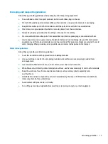
Equipment guidelines

Grounding equipment must include either a wrist strap or a foot strap at a grounded workstation.

When seated, wear a wrist strap connected to a grounded system. Wrist straps are flexible straps with a 
minimum of one megohm ±10% resistance in the ground cords. To provide proper ground, wear a strap 
snugly against the skin at all times. On grounded mats with banana-plug connectors, use alligator clips 
to connect a wrist strap.

When standing, use foot straps and a grounded floor mat. Foot straps (heel, toe, or boot straps) can be 
used at standing workstations and are compatible with most types of shoes or boots. On conductive 
floors or dissipative floor mats, use foot straps on both feet with a minimum of one megohm resistance 
between the operator and ground. To be effective, the conductive must be worn in contact with the skin.

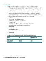
The following grounding equipment is recommended to prevent electrostatic damage:

Antistatic tape

Antistatic smocks, aprons, and sleeve protectors

Conductive bins and other assembly or soldering aids

Nonconductive foam

Conductive tabletop workstations with ground cords of one megohm resistance

Static-dissipative tables or floor mats with hard ties to the ground

Field service kits

Static awareness labels

Material-handling packages

Nonconductive plastic bags, tubes, or boxes

Metal tote boxes

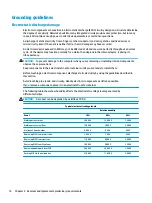
Electrostatic voltage levels and protective materials

The following table lists the shielding protection provided by antistatic bags and floor mats.

Material

Use

Voltage protection level

Antistatic plastics

Bags

1,500 V

Carbon-loaded plastic

Floor mats

7,500 V

Metallized laminate

Floor mats

5,000 V

18

Chapter 4   Removal and replacement preliminary requirements

Содержание chromebook 13 g1

Страница 1: ...HP Chromebook 13 G1 Maintenance and Service Guide IMPORTANT This document is intended for HP authorized service providers only ...

Страница 2: ...f Intel Corporation in the U S and other countries SD Logo is a trademark of its proprietor The information contained herein is subject to change without notice The only warranties for HP products and services are set forth in the express warranty statements accompanying such products and services Nothing herein should be construed as constituting an additional warranty HP shall not be liable for ...

Страница 3: ... another hard surface such as an adjoining optional printer or a soft surface such as pillows or rugs or clothing to block airflow Also do not allow the AC adapter to contact the skin or a soft surface such as pillows or rugs or clothing during operation The device and the AC adapter comply with the user accessible surface temperature limits defined by the International Standard for Safety of Info...

Страница 4: ...iv Safety warning notice ...

Страница 5: ...ts 13 4 Removal and replacement preliminary requirements 14 Tools required 14 Service considerations 14 Plastic parts 14 Cables and connectors 14 Drive handling 15 Grounding guidelines 16 Electrostatic discharge damage 16 Packaging and transporting guidelines 17 Workstation guidelines 17 5 Removal and replacement procedures 19 Component replacement procedures 19 Computer feet and base enclosure 19...

Страница 6: ...yboard top cover 30 Display assembly 31 6 Specifications 36 7 Power cord set requirements 37 Requirements for all countries 37 Requirements for specific countries and regions 38 8 Recycling 40 Index 41 vi ...

Страница 7: ...3 3 inch quarter high definition QHD AntiGlare 3200 1800 SVA white light emitting diode WLED ultraslim flat 2 6 mm 16 9 aspect ratio typical brightness 300 nits eDP non touch only Supports low voltage differential signaling LVDS Memory Supports Single Dual Channel LPDDR3 1866 MHZ on board system memory Supports up to 16 GB maximum on board system memory 4096MB 128MBx32x2 x4pcs 8192MB 256MBx16x4 x4...

Страница 8: ...tion 3 for unit ports 1 for Camera Keyboard pointing devices Full sized textured island style Google backlit keyboard TouchPad Multitouch gestures enabled Taps enabled as default Power requirements Supports a 3 cell 45 WHr 3 25 WHr polymer battery Supports a 45 W nPFC Type C Straight Type AC adapter Operating system Preinstalled Google Chrome OS operating system Serviceability End user replaceable...

Страница 9: ...ra Records video captures still photographs and provides HD high definition capability The antennas are not visible from the outside of the computer and antenna locations vary For optimal transmission keep the areas immediately around the antennas and sensors free from obstructions For wireless regulatory notices see the section of the Regulatory Safety and Environmental Notices that applies to yo...

Страница 10: ... the computer is on and you want to lock the screen press the power button until you see the sign in screen appear Pressing the power button during screen lock mode turns off the computer When the computer is on and you want to turn it off press and hold the button to lock the screen and then continue to press the button until the computer powers off 4 Chapter 2 External component identification ...

Страница 11: ...TouchPad Item Component Description TouchPad Moves the on screen pointer and selects or activates items on the screen TouchPad 5 ...

Страница 12: ...y power 3 USB 3 0 port Connects an optional USB device such as a keyboard mouse external drive or USB hub 4 Audio out headphone Audio in microphone combo jack Connects optional powered stereo speakers headphones earbuds a headset or a television audio cable Also connects an optional headset microphone This jack does not support optional microphone only devices WARNING To reduce the risk of persona...

Страница 13: ...are or access information To insert a card 1 Hold the card label side up with connectors facing the computer 2 Insert the card into the memory card reader and then press in on the card until it is firmly seated To remove a card Press in on the card and then remove it from the memory card reader Right side 7 ...

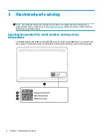
Страница 14: ... com select your country or region and then follow the on screen instructions Locating the product ID serial number and warranty information The label 1 with product ID 2 serial number 3 and warranty information 4 is located on the bottom of the computer This information may be needed when travelling internationally or when contacting support 8 Chapter 3 Illustrated parts catalog ...

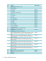
Страница 15: ... Component Spare part number 1 Display assembly The display assembly is spared at the subcomponent level only For more display assembly spare part information see Display assembly subcomponents on page 11 Computer major components 9 ...

Страница 16: ... Celeron M3 6Y30 0 9 GHz SC turbo up to 2 2 GHz dual core processor 2 0 GB L2 cache 1333 MHz FSB 4 5 W 4 0 GB of system memory and 16 GB of eMMC system storage 859518 001 Equipped with an Intel Celeron M5 6Y57 1 1 GHz SC turbo up to 2 2 GHz dual core processor 4 0 GB L2 cache 1333 MHz FSB 4 5 W 4 GB of system memory and 16 GB of eMMC system storage 859519 001 Equipped with an Intel Celeron M5 6Y57...

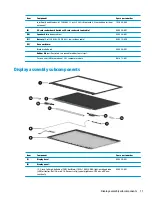
Страница 17: ...ble 848212 850 12 Base enclosure Black matte finish 859526 001 Rubber Kit not illustrated two reusable rubber feet strips For use on all HP Chromebook 13 G1 computer models 861673 001 Display assembly subcomponents Item Component Spare part number 1 Display bezel 859529 001 2 Display panel 13 3 inch full high definition FHD AntiGlare 1920 1080 UWVA light emitting diode LED ultraslim flat 2 6 mm 16...

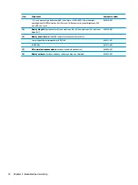
Страница 18: ... Hinge Kit includes outer left and right caps 3a left and right caps 3b and inner hinge 3c 859530 001 4 Display panel cable includes HD camera microphone module cable Low voltage differential signaling LVDS FHD 859531 001 LVDA QHD 861672 001 5 HD camera microphone module includes double sided adhesive 862692 001 6 Display enclosure includes antennas rubber padding and shielding 859532 001 12 Chapt...

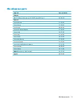
Страница 19: ...l 398063 001 For use in The Dominican Republic 213349 001 For use in India 404827 001 For use in Italy 213352 001 For use in Japan 349756 001 For use in North America 213349 001 For use in Switzerland 213354 001 For use in the United Kingdom and Singapore 213351 001 For use in Thailand 285096 001 For use in Taiwan 393313 001 Rubber Kit includes two rubber feet strips 861673 001 Screw Kit 859525 00...

Страница 20: ... the RMA shim process This will reactivate the TouchPad firmware If this does not fix the issue replace the TouchPad through warranty service Plastic parts CAUTION Using excessive force during disassembly and reassembly can damage plastic parts Use care when handling the plastic parts Apply pressure only at the points designated in the maintenance instructions Cables and connectors CAUTION When se...

Страница 21: ...avoid touching the connector Before removing a diskette drive or optical drive be sure that a diskette or disc is not in the drive and be sure that the optical drive tray is closed Handle drives on surfaces covered with at least one inch of shock proof foam Avoid dropping drives from any height onto any surface After removing a drive place it in a static proof bag Avoid exposing a drive to product...

Страница 22: ...s Keep components in their electrostatic safe containers until you are ready to install them Before touching an electronic component discharge static electricity by using the guidelines described in this section Avoid touching pins leads and circuitry Handle electronic components as little as possible If you remove a component place it in an electrostatic safe container The following table shows h...

Страница 23: ... to ground and that proper materials are selected to avoid static charging When grounding is not possible use an ionizer to dissipate electric charges Workstation guidelines Follow these grounding workstation guidelines Cover the workstation with approved static shielding material Use a wrist strap connected to a properly grounded work surface and use properly grounded tools and equipment Use cond...

Страница 24: ...n the operator and ground To be effective the conductive must be worn in contact with the skin The following grounding equipment is recommended to prevent electrostatic damage Antistatic tape Antistatic smocks aprons and sleeve protectors Conductive bins and other assembly or soldering aids Nonconductive foam Conductive tabletop workstations with ground cords of one megohm resistance Static dissip...

Страница 25: ...n during removal and replacement Computer feet and base enclosure Description Spare part number Computer feet included in the rubber kit 861673 001 Base enclosure 859526 001 Before replacing the computer feet and base enclosure follow these steps 1 Turn off the computer If you are unsure whether the computer is off or in Hibernation turn the computer on and then shut it down through the operating ...

Страница 26: ... base enclosure 1 Remove the two computer feet see Computer feet and base enclosure on page 19 2 Remove the five screws 1 3 Remove the remaining six screws 2 that secure the keyboard top cover to the base enclosure 4 Lift the edges and remove the base enclosure 3 20 Chapter 5 Removal and replacement procedures ...

Страница 27: ...ct the power from the computer by unplugging the power cord from the computer 3 Disconnect all external devices from the computer 4 Remove the two computer feet and base enclosure see Computer feet and base enclosure on page 19 Remove the battery 1 Disconnect the battery cable 1 from the computer 2 Remove the two screws 2 that secure the battery to the system board 3 Remove the battery 3 Reverse t...

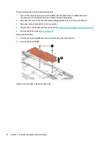
Страница 28: ... by unplugging the power cord from the computer 3 Disconnect all external devices from the computer 4 Remove the computer feet and base enclosure see Computer feet and base enclosure on page 19 5 Remove the battery see Battery on page 21 Remove the heat sink 1 Remove the two screws 1 that secure the heat sink to the system board 2 Remove the heat sink 2 Reverse this procedure to install the heat s...

Страница 29: ...Hibernation turn the computer on and then shut it down through the operating system 2 Disconnect the power from the computer by unplugging the power cord from the computer 3 Disconnect all external devices from the computer 4 Remove the two computer feet and base enclosure see Computer feet and base enclosure on page 19 5 Remove the battery see Battery on page 21 6 Remove the heat sink see Heat si...

Страница 30: ...to prevent incorrect installation NOTE If the WLAN antenna is not connected to the terminal on the WLAN module a protective sleeve must be installed on each antenna connector as shown in the following illustration Reverse this procedure to install the WLAN module 24 Chapter 5 Removal and replacement procedures ...

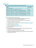
Страница 31: ...ard follow these steps 1 Turn off the computer If you are unsure whether the computer is off or in Hibernation turn the computer on and then shut it down through the operating system 2 Disconnect the power from the computer by unplugging the power cord from the computer 3 Disconnect all external devices from the computer 4 Remove the two computer feet and base enclosure see Computer feet and base ...

Страница 32: ...sconnect the speakers from the system board 5 5 Gently lift the system board 1 6 Remove the system board 2 Reverse this procedure to install the system board 26 Chapter 5 Removal and replacement procedures ...

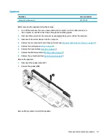
Страница 33: ... the power cord from the computer 3 Disconnect all external devices from the computer 4 Remove the two computer feet and base enclosure see Computer feet and base enclosure on page 19 5 Remove the battery see Battery on page 21 6 Remove the heat sink see Heat sink on page 21 7 Remove the WLAN module see WLAN module on page 23 8 Remove the system board see System board on page 25 Remove the speaker...

Страница 34: ...C adapter from the computer 4 Remove the two computer feet and base enclosure see Computer feet and base enclosure on page 19 5 Remove the battery see Battery on page 21 6 Remove the heat sink see Heat sink on page 21 7 Remove the WLAN module see WLAN module on page 23 Remove the SD card reader board 1 Release the connector 1 to which the SD card reader board cable is attached and then disconnect ...

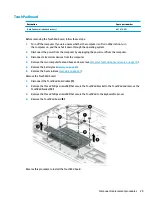
Страница 35: ...rnal devices from the computer 4 Remove the two computer feet and base enclosure see Computer feet and base enclosure on page 19 5 Remove the battery see Battery on page 21 6 Remove the heat sink see Heat sink on page 21 Remove the TouchPad board 1 Disconnect the TouchPad board cable 1 2 Remove the three Phillips screws 2 that secure the TouchPad bracket to the TouchPad and remove the TouchPad bra...

Страница 36: ...1 Before removing the keyboard top cover follow these steps 1 Turn off the computer If you are unsure whether the computer is off or in Hibernation turn the computer on and then shut it down through the operating system 2 Disconnect the power from the computer by unplugging the power cord from the computer 3 Disconnect all external devices from the computer 4 Remove the two computer feet and base ...

Страница 37: ...en shut it down through the operating system 2 Disconnect the power from the computer by unplugging the power cord from the computer 3 Disconnect all external devices from the computer 4 Remove the two computer feet and base enclosure see Computer feet and base enclosure on page 19 5 Remove the battery see Battery on page 21 6 Remove the heat sink see Heat sink on page 21 7 Remove the WLAN module ...

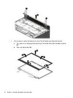
Страница 38: ...splay bezel or any of the LED display assembly subcomponents a Use a plastic tool to disengage the bezel starting at the top 1 left and right sides 2 and bottom 3 b Remove the display bezel 4 32 Chapter 5 Removal and replacement procedures ...

Страница 39: ...up and forward until it rests upside down in front of the display enclosure Remove the tape covering the display panel connector 2 disconnect it from the display panel 3 and then remove the panel 5 If it is necessary to replace the hinge brackets a Remove the two Phillips screws from the left and right outer caps 1 and the three Phillips screws from the hinge 2 Component replacement procedures 33 ...

Страница 40: ...f it is necessary to replace the camera module CAUTION Handle the module with caution This module has a thin profile and is susceptible to damage when not handled carefully a Detach the camera 1 from the display enclosure The module is attached to the display enclosure with double sided adhesive b Lift the module 2 34 Chapter 5 Removal and replacement procedures ...

Страница 41: ... using spare part number 862692 001 7 If it is necessary to replace the display cable a Release the cable from the routing path 1 along the display enclosure b Remove the cable 2 Reverse this procedure to reassemble install the display assembly Component replacement procedures 35 ...

Страница 42: ...0 C to 60 C 4 F to 140 F Relative humidity noncondensing Operating 10 to 90 Nonoperating 5 to 95 Maximum altitude unpressurized Operating 15 m to 3 048 m 50 ft to 10 000 ft Nonoperating 15 m to 12 192 m 50 ft to 40 000 ft NOTE Applicable product safety standards specify thermal limits for plastic surfaces The device operates well within this range of temperatures 36 Chapter 6 Specifications ...

Страница 43: ...equirements are applicable to all countries and regions The length of the power cord set must be at least 1 0 m 3 3 ft and no more than 2 0 m 6 5 ft All power cord sets must be approved by an acceptable accredited agency responsible for evaluation in the country or region where the power cord set will be used The power cord sets must have a minimum current capacity of 10 A and a nominal voltage ra...

Страница 44: ...Korea KTL 5 Sweden SEMKO 1 Switzerland SEV 1 Taiwan BSMI 6 Thailand TISI 1 The United Kingdom ASTA 1 The United States UL 2 1 The flexible cord must be Type HO5VV F 3 conductor 0 75 mm conductor size Power cord set fittings appliance coupler and wall plug must bear the certification mark of the agency responsible for evaluation in the country or region where it will be used 2 The flexible cord mus...

Страница 45: ...CCC certification mark 5 The flexible cord must be Type H05VV F 3 conductor 0 75 mm conductor size KTL logo and individual approval number must be on each element Corset approval number and logo must be printed on a flag label 6 The flexible cord must be Type HVCTF 3 conductor 1 25 mm conductor size Power cord set fittings appliance coupler cable and wall plug must bear the BSMI certification mark...

Страница 46: ...in general household waste Follow the local laws and regulations in your area for battery disposal HP encourages customers to recycle used electronic hardware HP original print cartridges and rechargeable batteries For more information about recycling programs see the HP Web site at http www hp com recycle 40 Chapter 8 Recycling ...

Страница 47: ...15 E electrostatic discharge 16 equipment guidelines 18 F feet removal 19 spare part numbers 19 G graphics product description 1 grounding guidelines 16 guidelines equipment 18 grounding 16 packaging 17 transporting 17 workstation 17 H headphone jack 6 heat sink removal 21 spare part number 10 21 hinge spare part number 12 J jacks audio in 6 audio out 6 headphone 6 microphone 6 K keyboard top cove...

Страница 48: ...tion 2 Speaker Kit spare part number 11 27 speakers removal 27 spare part number 11 27 storage product description 1 system board removal 25 spare part numbers 10 25 T tools required 14 TouchPad board removal 29 spare part numbers 10 29 TouchPad component 5 TouchPad zone 5 transporting guidelines 17 V video product description 1 W webcam light 3 webcam module removal 34 spare part number 35 webcam...

Отзывы: