background image


Removal and replacement procedures  56 

2.


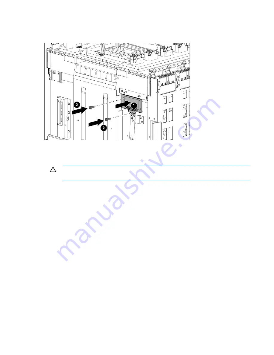
Route the cable between the Insight Display signal pass-thru board pin guide and the screw mounts. Be 
careful not to pinch the cable between the Insight Display signal pass-thru board and the screw mount 

as shown in the following figure. 


3.


Place the Insight Display signal pass-thru board properly over the guide pin and the screw mount and 
screw the Insight Display signal pass-thru board to the rear cage assembly. 

To verify the enclosure serial number: 


CAUTION: 

  Failure to complete the following procedure might cause inaccurate or incomplete 

information to appear in HP SIM and Onboard Administrator. 


1.


Using the Insight Display, navigate to the 

Enclosure Info

 screen. 

2.


Verify that the enclosure serial number matches the enclosure serial number on the label on the 
enclosure mounting bracket. 

o


If the enclosure serial number matches the label, continue to step 7. 

o


If the enclosure serial number does not appear or does not match the label, continue to step 3 to 
manually update the enclosure identity using the Onboard Administrator CLI. 

3.


Use the Onboard Administrator service port address found on the 

Enclosure Info

 screen to log in to the 

Onboard Administrator CLI with the 

Administrator

 local account password by using one of the 

following options: 

o


A serial cable attached to the Onboard Administrator serial port 

o


An Ethernet CAT5 cable attached to the enclosure service port that is the enclosure link uplink port 

4.


Enter the 

SET ENCLOSURE PART_NUMBER X

 command, where 

X


represents the 10-digit enclosure PID 

number found on the enclosure front label. 

5.


Enter the 

SET ENCLOSURE SERIAL_NUMBER Y

 command, where 

Y

 represents the 10-digit serial 

number found on the enclosure front label. 

6.


Enter the 

SET ENCLOSURE PDU_TYPE Z

 command, where 

Z

 represents the number of the appropriate 

power configuration: 

o


1—Single phase power, U.S. 

o


2—Three-phase power, U.S. 

o


3—Three-phase power, International 

Содержание BladeSystem c7000

Страница 1: ...perienced service technician HP assumes you are qualified in the servicing of computer equipment and trained in recognizing hazards in products with hazardous energy levels and are familiar with weight and stability precautions for rack installations Part Number 413336 014 June 2014 Edition 14 ...

Страница 2: ...r HP products and services are set forth in the express warranty statements accompanying such products and services Nothing herein should be construed as constituting an additional warranty HP shall not be liable for technical or editorial errors or omissions contained herein Microsoft and Windows are U S registered trademarks of Microsoft Corporation ...

Страница 3: ...elf 31 Half height or full height blade 34 HP BladeSystem Insight Display 36 Fan blank 38 Active Cool 200 fan 39 Interconnect blank 39 Enclosure front bezels Platinum models only 40 Interconnect switch or Pass Thru module 40 Interconnect bay dividers 41 Onboard Administrator blank 42 Onboard Administrator 43 Onboard Administrator tray 43 AC input module 44 AC control module 45 Rear cage 45 Insight...

Страница 4: ...ay numbering 66 HP BladeSystem Insight Display 67 Enclosure rear components 68 Interconnect module bay numbering 69 Onboard Administrator components 70 Onboard Administrator LEDs and buttons 71 Onboard Administrator with KVM LEDs and buttons 71 Fan bay numbering 72 Fan LED 72 Specifications 74 Environmental specifications 74 Enclosure specifications 74 Power specifications 75 DC power 75 Single ph...

Страница 5: ...n will help you over the telephone HP specifies in the materials shipped with a replacement CSR part whether a defective part must be returned to HP In cases where it is required to return the defective part to HP you must ship the defective part back to HP within a defined period of time normally five 5 business days The defective part must be returned with the associated documentation in the pro...

Страница 6: ...ine la société de courses ou le transporteur à utiliser Pour plus d informations sur le programme CSR de HP contactez votre Mainteneur Agrée local Pour plus d informations sur ce programme en Amérique du Nord consultez le site Web HP http www hp com go selfrepair Service de garantie pièces seules Votre garantie limitée HP peut inclure un service de garantie pièces seules Dans ce cas les pièces de ...

Страница 7: ... Self Repair um Reparaturzeiten zu minimieren und höhere Flexibilität beim Austausch defekter Bauteile zu ermöglichen Wenn HP oder ein HP Servicepartner bei der Diagnose feststellt dass das Produkt mithilfe eines CSR Teils repariert werden kann sendet Ihnen HP dieses Bauteil zum Austausch direkt zu CSR Teile werden in zwei Kategorien unterteilt Zwingend Teile für die das Customer Self Repair Verfa...

Страница 8: ...tegorías Obligatorio componentes para los que la reparación por parte del usuario es obligatoria Si solicita a HP que realice la sustitución de estos componentes tendrá que hacerse cargo de los gastos de desplazamiento y de mano de obra de dicho servicio Opcional componentes para los que la reparación por parte del usuario es opcional Estos componentes también están diseñados para que puedan ser r...

Страница 9: ...orieën CSR onderdelen Verplicht Onderdelen waarvoor reparatie door de klant verplicht is Als u HP verzoekt deze onderdelen voor u te vervangen worden u voor deze service reiskosten en arbeidsloon in rekening gebracht Optioneel Onderdelen waarvoor reparatie door de klant optioneel is Ook deze onderdelen zijn ontworpen voor reparatie door de klant Als u echter HP verzoekt deze onderdelen voor u te v...

Страница 10: ...ependendo do tipo de serviço de garantia destinado ao produto OBSERVAÇÃO Algumas peças da HP não são projetadas para o reparo feito pelo cliente A fim de cumprir a garantia do cliente a HP exige que um técnico autorizado substitua a peça Essas peças estão identificadas com a marca No Não no catálogo de peças ilustrado Conforme a disponibilidade e o local geográfico as peças CSR serão enviadas no p...

Страница 11: ...Customer self repair 11 No caso desse serviço a substituição de peças CSR é obrigatória Se desejar que a HP substitua essas peças serão cobradas as despesas de transporte e mão de obra do serviço ...

Страница 12: ...Customer self repair 12 ...

Страница 13: ...Customer self repair 13 ...

Страница 14: ...Customer self repair 14 ...

Страница 15: ... 2 Rear cage 3 Hardware kit 432463 001 Mandatory1 a Device bay shelf b Vertical cable cover c Left LCD cap 4 Device bay blank 414051 001 Mandatory1 5 Fan blank 414052 001 Mandatory1 6 Power supply blank 416043 001 Mandatory1 7 Onboard Administrator blank 414054 001 Mandatory1 8 Interconnect blank 414053 001 Mandatory1 9 Plastics kit 414063 001 Mandatory1 a Left handle cover ...

Страница 16: ...sse s appliquer HP exige que le remplacement de la pièce soit effectué par un Mainteneur Agréé Ces pièces sont identifiées par la mention Non dans le Catalogue illustré 1 Mandatory Obbligatorie Parti che devono essere necessariamente riparate dal cliente Se il cliente ne affida la riparazione ad HP deve sostenere le spese di spedizione e di manodopera per il servizio 2 Optional Opzionali Parti la ...

Страница 17: ...reparatie door de klant Als u echter HP verzoekt deze onderdelen voor u te vervangen kunnen daarvoor extra kosten in rekening worden gebracht afhankelijk van het type garantieservice voor het product 3 No Nee Sommige HP onderdelen zijn niet ontwikkeld voor reparatie door de klant In verband met de garantievoorwaarden moet het onderdeel door een geautoriseerde Service Partner worden vervangen Deze ...

Страница 18: ...1 Mandatory1 c HP BL7000 2400W Platinum power supply 588733 001 Mandatory1 d HP BladeSystem c7000 DC power supply 544660 001 Mandatory1 14 HP BladeSystem Insight Display a 7 62 3 00 in Insight Display 441203 001 No3 b 7 62 cm 3 00 in Insight Display RoHS 519349 001 No3 c 5 08 cm 2 00 in Insight Display 415839 001 No3 15 Location discovery services board 709865 001 Mandatory1 16 Insight Display pas...

Страница 19: ...nte ne richiede la sostituzione ad HP potrebbe dover sostenere spese addizionali a seconda del tipo di garanzia previsto per il prodotto 3 No Non CSR Alcuni componenti HP non sono progettati per la riparazione da parte del cliente Per rispettare la garanzia HP richiede che queste parti siano sostituite da un centro di assistenza autorizzato Tali parti sono identificate da un No nel Catalogo illust...

Страница 20: ...streerde onderdelencatalogus aangemerkt met Nee 1 Mandatory Obrigatória Peças cujo reparo feito pelo cliente é obrigatório Se desejar que a HP substitua essas peças serão cobradas as despesas de transporte e mão de obra do serviço 2 Optional Opcional Peças cujo reparo feito pelo cliente é opcional Essas peças também são projetadas para o reparo feito pelo cliente No entanto se desejar que a HP as ...

Страница 21: ... BladeSystem 414037 001 Mandatory1 b HP GbE2c Layer 2 3 Ethernet Blade Switch for c Class BladeSystem 438475 001 Mandatory1 c HP 10Gb Ethernet BL c Switch 447116 001 Mandatory1 d HP 1 10Gb Ethernet BL c Switch 438476 001 Mandatory1 e Brocade 4Gb SAN Switch for HP c Class BladeSystem 12 ports 411120 001 Mandatory1 f Brocade 4Gb SAN switch for HP c Class BladeSystem 24 ports 411121 001 Mandatory1 ...

Страница 22: ...th power pack and licensed features 489866 001 Mandatory1 r HP BLc Cisco 1 10GbE 3120X Switch 451357 001 Mandatory1 s HP BLc Cisco 1GbE 3120G Switch 451356 001 Mandatory1 t HP 6120G BX Blade Switch 508090 001 Mandatory1 u Switch 10Gb Ethernet c Class 517994 001 Mandatory1 v Module BLc VC8Gb 20 Port FC 572216 001 Mandatory1 w HP BLc VC Flex 10 10D Module 639852 001 Mandatory1 x HP Virtual Connect F...

Страница 23: ...ure models 681840 b21 681842 b21 681844 b21 763850 b21 1 Mandatory Parts for which customer self repair is mandatory If you request HP to replace these parts you will be charged for the travel and labor costs of this service 2 Optional Parts for which customer self repair is optional These parts are also designed for customer self repair If however you require that HP replace them for you there ma...

Страница 24: ...drá que hacerse cargo de los gastos de desplazamiento y de mano de obra de dicho servicio 2 Optional Opcional componentes para los que la reparación por parte del usuario es opcional Estos componentes también están diseñados para que puedan ser reparados por el usuario Sin embargo si precisa que HP realice su sustitución puede o no conllevar costes adicionales dependiendo del tipo de servicio de g...

Страница 25: ...Illustrated parts catalog 25 ...

Страница 26: ...ontainers Keep electrostatic sensitive parts in their containers until they arrive at static free workstations Place parts on a grounded surface before removing them from their containers Avoid touching pins leads or circuitry Always be properly grounded when touching a static sensitive component or assembly Warning and caution messages WARNING To reduce the risk of personal injury or damage to eq...

Страница 27: ... the equipment you must adequately support enclosures during installation and removal WARNING Always use at least two people to lift an enclosure into the rack If the enclosure is being loaded into the rack above chest level a third person must assist with aligning the enclosure with the rails while the other two people support the weight of the enclosure WARNING Before installing an enclosure in ...

Страница 28: ...lity UPS device This device protects the hardware from damage caused by power surges and voltage spikes and keeps the system in operation during a power failure Preparing the enclosure To service any internal enclosure component complete the following actions Power down all server blades or workstation blades Power down the server blades or workstation blades on page 28 Power down all storage blad...

Страница 29: ...orkstation blades is in standby mode auxiliary power is still being provided To remove all power from the server blades or workstation blades remove the server blades or workstation blades from the enclosure After initiating a virtual power down command be sure that the server blades or workstation blades is in standby mode by observing that the system power LED is amber Power down the storage bla...

Страница 30: ...tinum or 48vDC power supplies in one enclosure Install only one type of power supply in a single enclosure NOTE To access all power supply bays slide the HP BladeSystem Insight Display to the right or left To remove the component 1 Press the release button 2 Pull down the handle 3 Remove the power supply or the power supply blank CAUTION For best cooling practices do not operate the enclosure for ...

Страница 31: ...verse the removal procedure Device bay shelf The c7000 enclosure is divided into four quadrants by the vertical support metal work Within each quadrant a removable divider supports half height blades To install a full height blade in any quadrant this divider must be removed Therefore a quadrant can only contain either full height blades or half height blades CAUTION Failure to install the divider...

Страница 32: ... as both full height and half height blades A bracket ships with each SB40c Storage Blade that allows a half height blade to be mounted on top of the storage blade The lower tape or storage blade cannot be removed without first removing the upper half height blade To remove the component 1 Remove any components in the device bays o Device bay blank o Half height or full height blade ...

Страница 33: ... 2 Slide the device bay shelf locking tab to the left to open it 3 Push the device bay shelf back until it stops lift the right side slightly to disengage the two tabs from the divider wall and then rotate the right edge downward clockwise ...

Страница 34: ...ation of components see the appropriate HP BladeSystem c Class enclosure setup and installation guide The c7000 enclosure is divided into four quadrants by the vertical support metal work Within each quadrant a removable divider supports half height blades To install a full height blade in any quadrant this divider must be removed Therefore a quadrant can only contain either full height blades or ...

Страница 35: ...rage Blade that allows a half height blade to be mounted on top of the storage blade The lower tape or storage blade cannot be removed without first removing the upper half height blade To remove the component 1 Identify the proper half height or full height blade in the enclosure Device bay numbering on page 64 2 Back up all data 3 Power down the half height or full height blade Power down the se...

Страница 36: ...s with more than one component or blank removed When removing an active component replace it with a blank To replace the component reverse the removal procedure HP BladeSystem Insight Display To remove the component 1 Power down the enclosure on page 29 2 Remove the following components o Half height blades bays 9 13 Half height or full height blade on page 34 ...

Страница 37: ...lanks bays 1 4 HP BladeSystem c7000 power supply or power supply blank on page 30 3 Remove the three T 15 Torx screws that secure the Insight Display cable center cover and then remove the cover 4 Disconnect the Insight Display cable 5 Remove the two T 10 Torx screws that secure the Insight Display 6 Remove the upper brace 7 Tilt the Insight Display forward and remove it from the enclosure ...

Страница 38: ...emoval procedure Fan blank To remove the component 1 Turn the handle counterclockwise 2 Remove the blank CAUTION For best cooling practices do not operate the enclosure for extended periods with more than one component or blank removed When removing an active component replace it with a blank To replace the component reverse the removal procedure ...

Страница 39: ...move the component 1 Turn the handle counterclockwise 2 Remove the fan CAUTION For best cooling practices do not operate the enclosure for extended periods with more than one component or blank removed When removing an active component replace it with a blank To replace the component reverse the removal procedure When installing the bottom fans invert them so that the fan LED is in the top left co...

Страница 40: ...e than one component or blank removed When removing an active component replace it with a blank To replace the component slide the component into the bay until it locks into place Enclosure front bezels Platinum models only Remove the component as indicated To replace the component reverse the removal procedure Interconnect switch or Pass Thru module ...

Страница 41: ...transceiver or an SFP dust cover at all times 1 Disconnect all cables from the component 2 Press the release tab 3 Open the handle 4 Remove the interconnect switch or Pass Thru module CAUTION For best cooling practices do not operate the enclosure for extended periods with more than one component or blank removed When removing an active component replace it with a blank To replace the component re...

Страница 42: ...val procedure Onboard Administrator blank Remove the component as indicated CAUTION For best cooling practices do not operate the enclosure for extended periods with more than one component or blank removed When removing an active component replace it with a blank To replace the component reverse the removal procedure ...

Страница 43: ...t operate the enclosure for extended periods with more than one component or blank removed When removing an active component replace it with a blank To replace the component reverse the removal procedure Onboard Administrator tray To remove the component 1 Remove the Onboard Administrator modules Onboard Administrator on page 43 2 Remove the Onboard Administrator blanks Onboard Administrator blank...

Страница 44: ...ank removed When removing an active component replace it with a blank To replace the component reverse the removal procedure AC input module To remove the component 1 Power down the server blades Power down the server blades or workstation blades on page 28 2 Power down the enclosure on page 29 3 Loosen the two slotted T 15 Torx screws that secure the AC input module 4 Remove the AC input module ...

Страница 45: ...e and component connectors always remove or disengage and extend all blades and power supplies approximately 8 cm 3 in before removing or installing the rear cage WARNING To reduce the risk of personal injury or equipment damage at least two people are needed to safely move the rear cage IMPORTANT When removing components from the rear cage note their position for later replacement To remove the c...

Страница 46: ...ule on page 40 7 Remove the Onboard Administrator modules Onboard Administrator on page 43 8 Remove the Onboard Administrator tray Onboard Administrator tray on page 43 9 Remove the rear cage a Loosen the thumbscrews and then open the hinges completely b Use the handles to extend the rear cage until the release levers engage on both sides of the rear cage c Grasp the handholds below the release le...

Страница 47: ...nd component connectors always remove or disengage and extend all blades and power supplies approximately 8 cm 3 in before removing or installing the rear cage To remove the component 1 Power down the server blades Power down the server blades or workstation blades on page 28 2 Power down the enclosure on page 29 3 Disconnect all cables 4 Remove the half height and full height blades Half height o...

Страница 48: ...o people are needed to safely move the rear cage 12 Remove the three T 15 Torx screws that secure the Insight Display cable center cover and then remove the cover 13 Disconnect the Insight Display cable 14 Remove the four T 15 Torx screws that secure the interconnect board cover and then remove the cover NOTE The device bay walls have been removed for clarity ...

Страница 49: ...ay signal pass thru board WARNING To reduce the risk of damage to the midplane and component connectors always remove or disengage and extend all blades and power supplies approximately 8 cm 3 in before removing or installing the rear cage To remove the component 1 Power down the server blades Power down the server blades or workstation blades on page 28 2 Power down the enclosure on page 29 3 Dis...

Страница 50: ...fan on page 39 6 Remove the interconnect switches and Pass Thru modules Interconnect switch or Pass Thru module on page 40 7 Remove the Onboard Administrator modules Onboard Administrator on page 43 Remove the Onboard Administrator tray Onboard Administrator tray on page 43 8 Remove the rear cage Rear cage on page 45 WARNING To reduce the risk of personal injury or equipment damage at least two pe...

Страница 51: ...o replace the component reverse the removal procedure Location discovery services board Platinum models only To remove the component 1 Power down the server blades Power down the server blades or workstation blades on page 28 2 Power down the enclosure on page 29 3 Remove the handle cover ...

Страница 52: ...Removal and replacement procedures 52 4 Remove the location discovery services board cover 5 Disconnect the cable from the location discovery services board ...

Страница 53: ... Administrator version 3 20 and later automatically restores the enclosure identity including the serial number PID and PDU type if a midplane assembly replacement is detected This firmware feature requires that the original Onboard Administrator modules and all original fans be reinstalled along with all power supplies before installing any other blade or interconnect module All power supply modu...

Страница 54: ...nclosure fans Active Cool 200 fan on page 39 6 Remove the interconnect switches and Pass Thru modules Interconnect switch or Pass Thru module on page 40 7 Remove the Onboard Administrator modules Onboard Administrator on page 43 8 Remove the Onboard Administrator tray Onboard Administrator tray on page 43 CAUTION When removing the rear cage and midplane assembly the connectors on the midplane asse...

Страница 55: ...o replace the midplane assembly reverse the removal procedure CAUTION The LCD cable must be correctly routed for proper operation To route the LCD cable 1 When installing the midplane assembly onto the rear cage assembly ensure the LCD cable is routed behind the interconnect module rubber boot and through the sheet metal gaps Route the cable as shown in the following figure ...

Страница 56: ...matches the label continue to step 7 o If the enclosure serial number does not appear or does not match the label continue to step 3 to manually update the enclosure identity using the Onboard Administrator CLI 3 Use the Onboard Administrator service port address found on the Enclosure Info screen to log in to the Onboard Administrator CLI with the Administrator local account password by using one...

Страница 57: ...tall all VC Ethernet modules VC FC modules and all other interconnect modules in the same bay they were removed from 8 Reconnect all cables to those modules to the same ports they were removed from 9 Wait two minutes 10 Install all the server blades into the same bays they were removed from ...

Страница 58: ...Cabling 58 Cabling Single phase AC configuration Three phase AC configuration ...

Страница 59: ...nnectors for power supply bay 1 3 DC connectors for power supply bay 2 4 DC connectors for power supply bay 3 5 DC connectors for power supply bay 4 6 DC connectors for power supply bay 5 7 DC connectors for power supply bay 6 8 Chassis grounding lugs 9 48 VDC power connections 10 DC return power connections ...

Страница 60: ...t multiple devices a USB hub not included is required 3 Serial connector Serial RS232 DB 9 connector with PC standard pinout Connect a computer with a null modem serial cable to the Onboard Administrator command line interface CLI 4 VGA connector VGA DB 15 connector with PC standard pinout To access the KVM menu or Onboard Administrator CLI connect a VGA monitor or rack KVM monitor for enclosure K...

Страница 61: ...onnect multiple devices a USB hub not included is required 3 Serial connector Serial RS232 DB 9 connector with PC standard pinout Connect a computer with a null modem serial cable to the Onboard Administrator command line interface CLI 4 VGA connector VGA DB 15 connector with PC standard pinout To access the KVM menu or Onboard Administrator CLI connect a VGA monitor or rack KVM monitor for enclos...

Страница 62: ...in two ways OA GUI Enclosure settings Enclosure configuration scripts OA CLI Execute the following CLI command SHOW ALL Review this inventory report where appropriate and have this report on hand available when contacting HP Support For more information see the HP website http www hp com go OAlog Server blade diagnostic tools HP Insight Diagnostics HP Insight Diagnostics is a proactive server blad...

Страница 63: ...ated Management Log The IML records hundreds of events and stores them in an easy to view form The IML timestamps each event with 1 minute granularity You can view recorded events in the IML in several ways including the following From within HP SIM From within operating system specific IML viewers o For Windows IML Viewer o For Linux IML Viewer Application From within the iLO user interface From ...

Страница 64: ...sight Display 8 Power supply bay 5 9 Power supply bay 6 10 Air intake slot Do not block For more information see Device bay numbering on page 64 Device bay numbering Each enclosure requires interconnects to provide network access for data transfer Interconnects reside in bays located on the rear of the enclosure Be sure to review device bay numbering to determine which external network connections...

Страница 65: ...Component identification 65 IMPORTANT When looking at the rear of the enclosure front device bay numbering is reversed Full height device bay numbering Half height device bay numbering ...

Страница 66: ...Component identification 66 Power supply LEDs Power LED 1 green Fault LED 2 amber Condition Off Off No AC power to the power supply On Off Normal Off On Power supply failure Power supply bay numbering ...

Страница 67: ... Insight Display light turns off Pressing any button on the Insight Display reactivates the screen Amber The Insight Display background illuminates amber when the Onboard Administrator detects an error or alert condition Depending on the error the component is displayed in red or yellow on the Health Summary screen After 2 minutes of inactivity the Insight Display background flashes amber indicati...

Страница 68: ...row button Moves the menu or navigation bar selection left one position 3 Right arrow button Moves the menu or navigation bar selection right one position 4 OK button Accepts the highlighted selection and navigates to the selected menu 5 Down arrow button Moves the menu selection down one position 6 Up arrow button Moves the menu selection up one position Enclosure rear components ...

Страница 69: ...terconnect bay 6 9 Interconnect bay 8 10 Onboard Administrator bay 2 11 Power supply exhaust vent do not block 12 Fan bay 10 13 Fan bay 9 14 Fan bay 8 15 Fan bay 7 16 Fan bay 6 17 AC power connectors 18 Onboard Administrator bay 1 19 Interconnect bay 7 20 Interconnect bay 5 21 Interconnect bay 3 22 Interconnect bay 1 Interconnect module bay numbering ...

Страница 70: ...ine slot 2 then ports 1 and 2 are connected to interconnect bays 5 and 6 respectively and ports 3 and 4 are connected to interconnect bays 7 and 8 respectively If a four port option card is installed in mezzanine slot 3 in a full height server blades or workstation blades then ports 1 and 2 are connected to interconnect bays 7 and 8 respectively and ports 3 and 4 are connected to interconnect bays...

Страница 71: ...ription 1 Onboard Administrator UID LED 2 Enclosure UID LED and UID button 3 Onboard Administrator active LED 4 Onboard Administrator health LED 5 Onboard Administrator reset button Onboard Administrator with KVM LEDs and buttons Item Description 1 Onboard Administrator UID LED ...

Страница 72: ...Enclosure UID LED and UID button 3 Onboard Administrator health LED 4 Onboard Administrator active LED 5 Onboard Administrator reset button Fan bay numbering Fan LED LED color Fan status Solid green The fan is working Solid amber The fan has failed ...

Страница 73: ...Component identification 73 LED color Fan status Flashing amber See the Insight Display screen ...

Страница 74: ...icable No direct sunlight allowed Upper operating limit is 3 048 m 10 000 ft or 70 Kpa 10 1 psia Upper non operating limit is 9 144 m 30 000 ft or 30 3 KPa 4 4 psia Storage maximum humidity of 95 is based on a maximum temperature of 45 C 113 F Altitude maximum for storage corresponds to a pressure minimum of 70 KPa Enclosure specifications Specification Value Product dimensions Height 442 0 mm 17 ...

Страница 75: ...IEC 320 C19 C20 1 22 m 4 ft IEC 320 C19 C20 1 22 m 4 ft IEC 320 C19 C20 1 22 m 4 ft Output 2250 W per power supply 2450 W per power supply 2450 W per power supply Input requirements Rated input voltage 100 VAC to 124 VAC 200 VAC to 240 VAC 200 VAC to 240 VAC 200 VAC to 240 VAC Rated input frequency 50 Hz to 60 Hz 50 Hz to 60 Hz 50 Hz to 60 Hz Rated input current per power supply maximum 11 7 A at ...

Страница 76: ...cation HP BladeSystem c7000 Power Supply HP 2400W High Efficiency Power Supply HP BL7000 2400W Platinum Power Supply Power cords 2 IEC 309 200 346 V to 240 415 V 5 pin 16 A 2 44 m 10 ft IEC 309 200 346 V to 240 415 V 5 pin 16 A 2 44 m 10 ft IEC 309 200 346 V to 240 415 V 5 pin 16 A 2 44 m 10 ft Output 2250 W 2450 W 2450 W Input requirements Rated input voltage 346 VAC to 415 VAC line to line 200 V...

Страница 77: ...ations ADU Array Diagnostics Utility CSR Customer Self Repair ESD electrostatic discharge HVDC High Voltage DC iLO Integrated Lights Out IML Integrated Management Log OA Onboard Administrator SFP small form factor pluggable SIM Systems Insight Manager ...

Страница 78: ...oviding documentation that meets your needs To help us improve the documentation send any errors suggestions or comments to Documentation Feedback mailto docsfeedback hp com Include the document title and part number version number or the URL when submitting your feedback ...

Страница 79: ...elf 31 diagnostic tools 62 diagnostics utility 62 documentation 78 E electrostatic discharge 26 enclosure LEDs 64 enclosure specifications 74 enclosure configuring 67 environmental specifications 74 F fan bay numbering 72 fan blank 38 fan LED 72 fan location 39 features 64 front components 64 H half height blade shelf 31 HP BladeSystem Insight Display 36 67 HP BladeSystem Insight Display component...

Страница 80: ... P part numbers 15 18 pass thru module 40 power specifications 75 power supply 30 power supply blank 30 power supply enclosure bay numbering 64 powering down 28 29 preparation procedures 28 R rear cage 45 rear components 21 68 removal and replacement procedures 26 required tools 26 routing cables 53 S safety considerations 26 safety information 26 server blade removing 34 single phase AC configura...

Отзывы: