background image

Step 3: Connect power

Step 4: Verify switch operation

Step 5: Perform initial system boot

1. If the network operating system (NOS) installer is 

located on a network server, first connect the RJ-45 
Management (Mgmt) port to the network using 100-
ohm Category 5, 5e or better twisted-pair cable. (Not 
required if the NOS installer is located on attached 
storage.)

2. Boot the switch. Wait for the ONIE software to locate 

and execute the NOS installer, and then wait for the 
installer to load the NOS software image.

Subsequent switch boots will bypass ONIE and 
directly run the NOS software.

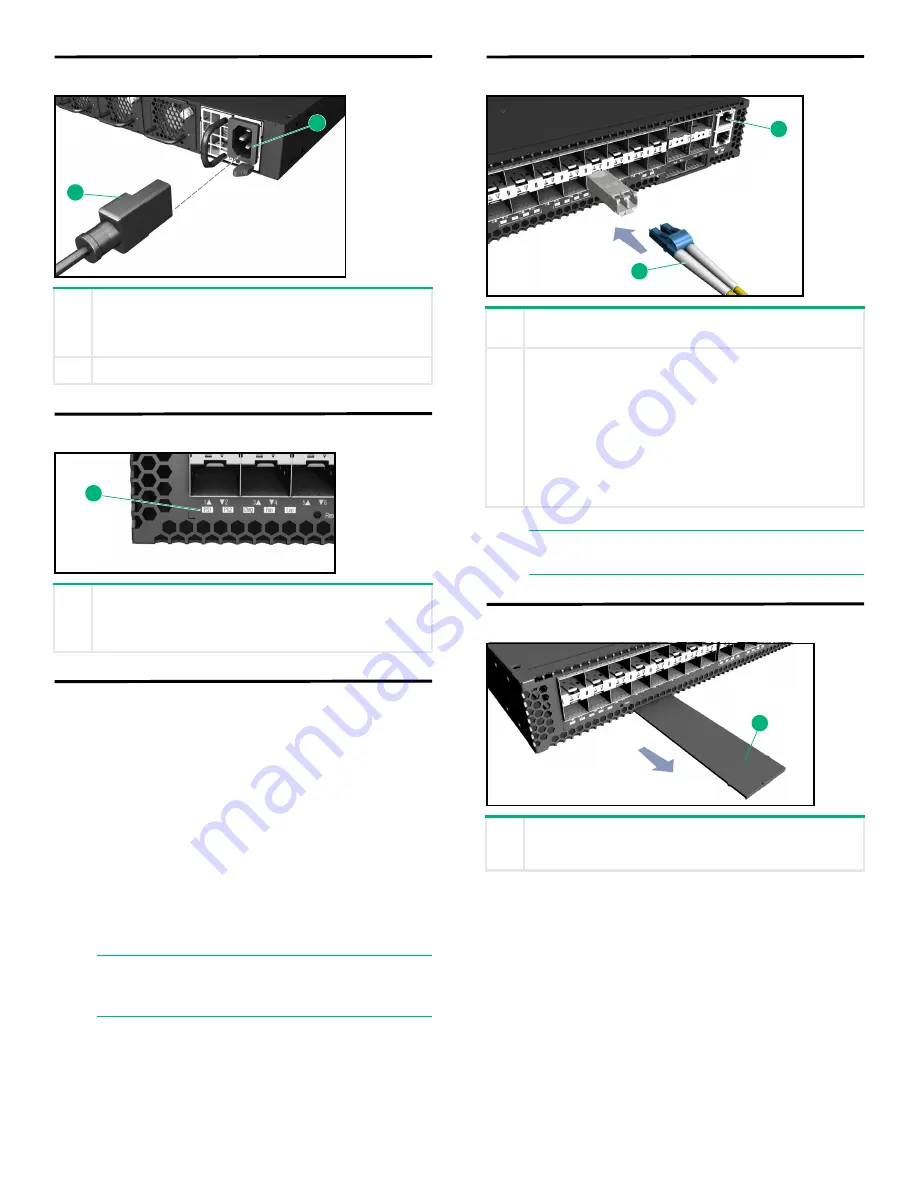
Step 6: Connect network cables

Step 7: View the product label

1

Install one or two universal AC power modules in the 

switch.

The switch supports up to two PSUs that must have the 

same matching airflow direction as the installed fan tray.

2

Connect an external AC power source to the modules.

1

Verify basic switch operation by checking the system 

LEDs.

When operating normally, the PSU1/PSU2, Diag, and 

Fan LEDs should all be on green.

NOTE:

    Refer to the network operating system 

(NOS) installer and NOS documentation for 
details on software options and set up for ONIE.

1

2

1

1

For the RJ-45 Management port, connect 100-ohm 

Category 5, 5e or better twisted-pair cable.

2

Connect DAC cables to the SFP+/QSFP+ slots. Or first 

install SFP+/QSFP+ transceivers and then connect fiber 

optic cabling to the transceiver ports. 

The following transceivers are supported:

40GBASE-CR4

40GBASE-SR4

10GBASE-CR

10GBASE-SR

1000BASE-SX

1000BASE-LX

NOTE:

    As connections are made, check the port 

status LEDs to be sure the links are valid.

1

The switch product label is located below SFP+ ports 7–

12 on left side of the front panel. Pull the label out to view 

the product information.

2

1

1

Содержание Altoline 6921

Страница 1: ...flow direction That is all modules must have a front to back F2B airflow direction or all modules must have a back to front B2F airflow direction The airflow direction of fan trays is indicated by text printed on the modules 1 Attach the brackets to the switch 2 Use the screws supplied with the rack to secure the switch in the rack CAUTION Installing the switch in a rack requires two people One pe...

Страница 2: ...hing airflow direction as the installed fan tray 2 Connect an external AC power source to the modules 1 Verify basic switch operation by checking the system LEDs When operating normally the PSU1 PSU2 Diag and Fan LEDs should all be on green NOTE Refer to the network operating system NOS installer and NOS documentation for details on software options and set up for ONIE 1 2 1 1 For the RJ 45 Manage...

Страница 3: ...a power cord displaying the mark of the safety agency that defines the regulations for power cords in your country region The mark is your assurance that the power cord can be used safely with the switch and power supply When installing the switch the AC outlet should be near the switch and should be easily accessible in case the switch must be powered off Ensure the switch does not overload the p...

Страница 4: ... such source code on CD DVD please send a check or money order in the amount of US 10 00 to Hewlett Packard Enterprise Attn HPN Open Source Query M S 5554 8000 Foothills Blvd Roseville CA 95747 USA Please specify the product and version for which you are requesting source code You may also request a copy of this source code by contacting the HPN Open Source Query Team via email at HPN Open Source ...

Отзывы: