background image

9.

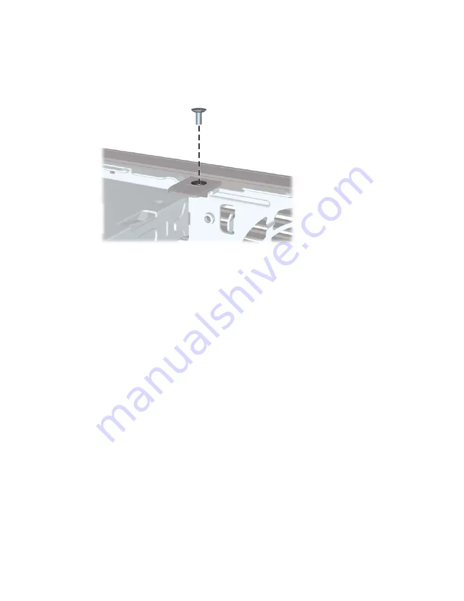
Install the security screw through the middle front bezel release tab and into the chassis to secure
the front bezel in place.

Figure C-9

  Installing the Front Bezel Security Screw

10.

Replace the access panel.

11.

If the computer was on a stand, replace the stand.

12.

Reconnect the power cord and turn on the computer.

13.

Lock any security devices that were disengaged when the access panel was removed.

ENWW

Installing a Security Lock

37

Содержание 8000f - Elite Ultra-slim Desktop PC

Страница 1: ...Hardware Reference Guide HP Compaq 8000f Elite Ultra Slim Desktop Business PC ...

Страница 2: ...ents accompanying such products and services Nothing herein should be construed as constituting an additional warranty HP shall not be liable for technical or editorial errors or omissions contained herein This document contains proprietary information that is protected by copyright No part of this document may be photocopied reproduced or translated to another language without the prior written c...

Страница 3: ...manner indicates that failure to follow directions could result in bodily harm or loss of life CAUTION Text set off in this manner indicates that failure to follow directions could result in damage to equipment or loss of information NOTE Text set off in this manner provides important supplemental information ENWW iii ...

Страница 4: ...iv About This Book ENWW ...

Страница 5: ...he Computer Access Panel 10 Removing and Replacing the Front Bezel 11 Removing a Bezel Blank 13 Changing from Desktop to Tower Configuration 14 Installing Additional Memory 15 SODIMMs 15 DDR3 SDRAM SODIMMs 15 Populating SODIMM Sockets 16 Installing SODIMMs 17 Replacing the Optical Drive 19 Removing the Existing Optical Drive 19 Preparing the New Optical Drive 20 Installing the New Optical Drive 20...

Страница 6: ...k 34 Front Bezel Security 35 Appendix D Electrostatic Discharge Preventing Electrostatic Damage 38 Grounding Methods 38 Appendix E Computer Operating Guidelines Routine Care and Shipping Preparation Computer Operating Guidelines and Routine Care 39 Optical Drive Precautions 40 Operation 40 Cleaning 40 Safety 40 Shipping Preparation 40 Index 41 vi ENWW ...

Страница 7: ...top computer comes with features that may vary depending on the model For a complete listing of the hardware and software installed in the computer run the diagnostic utility included on some computer models only Figure 1 1 Ultra Slim Desktop ENWW Standard Configuration Features 1 ...

Страница 8: ...tate Power Button NOTE When a device is plugged into the Microphone Headphone Connector a dialog box will pop up asking if you want to use the connector for a microphone line Line In device or a headphone You can reconfigure the connector at any time by double clicking the Realtek HD Audio Manager icon in the Windows taskbar NOTE The Power On Light is normally green when the power is on If it is f...

Страница 9: ...ector green 4 DisplayPort Monitor Connector 9 RJ 45 Network Connector 5 VGA Monitor Connector blue NOTE Arrangement and number of connectors may vary by model When a device is plugged into the blue Line In Audio Connector a dialog box will pop up asking if you want to use the connector for a line in device or a microphone You can reconfigure the connector at any time by double clicking the Realtek...

Страница 10: ...e the right mouse button to open pop up menus in a Microsoft Office application May perform other functions in other software applications 8 Windows Logo Keys1 Used to open the Start menu in Microsoft Windows Used in combination with other keys to perform other functions 9 Alt Keys Used in combination with another key their effect depends on the application software you are using 1 Keys available ...

Страница 11: ...nd select Windows Sidebar Windows Logo Key g Cycles through Sidebar gadgets Windows Logo Key t Cycles through programs on the taskbar Windows Logo Key u Launches Ease of Access Center Windows Logo Key any number key Launches the Quick Launch shortcut that is in the position that corresponds to the number for example Windows Logo Key 1 launches the first shortcut in the Quick Launch menu In additio...

Страница 12: ...and a product ID that are located on the top of the computer when it is in the tower configuration Keep these numbers available for use when contacting customer service for assistance Figure 1 5 Serial Number and Product ID Location 6 Chapter 1 Product Features ENWW ...

Страница 13: ...ccessible at all times To reduce the risk of serious injury read the Safety Comfort Guide It describes proper workstation setup posture and health and work habits for computer users and provides important electrical and mechanical safety information This guide is located on the Web at http www hp com ergo WARNING Energized and moving parts inside Disconnect power to the equipment before removing t...

Страница 14: ...p into a slot on the air vent to prevent the cord from becoming disconnected from the computer 2 3 Bundle any excess power cord with the supplied strap 3 4 Plug the female end of the other power cord into the power supply brick 4 5 Connect the other end of the power cord to an electrical outlet 5 Figure 2 1 Connecting the Power Cord CAUTION Failure to secure the power cable with the retainer clip ...

Страница 15: ... power outlet and disconnect any external devices CAUTION Regardless of the power on state voltage is always present on the system board as long as the system is plugged into an active AC outlet You must disconnect the power cord to avoid damage to the internal components of the computer 5 If the computer is on a stand remove the computer from the stand and lay the computer down 6 Loosen the thumb...

Страница 16: ...s on the panel with the slots on the chassis then slide the panel towards the front of the chassis until it stops 1 2 Tighten the thumbscrew to secure the access panel 2 Figure 2 3 Replacing the Computer Access Panel 10 Chapter 2 Hardware Upgrades ENWW ...

Страница 17: ...t any external devices CAUTION Regardless of the power on state voltage is always present on the system board as long as the system is plugged into an active AC outlet You must disconnect the power cord to avoid damage to the internal components of the computer 5 If the computer is on a stand remove the computer from the stand and lay the computer down 6 Remove the computer access panel 7 Lift up ...

Страница 18: ...p side of the bezel onto the chassis 2 and snap it into place Figure 2 5 Replacing the Front Bezel 2 Replace the access panel 3 If the computer was on a stand replace the stand 4 Reconnect the power cord and turn on the computer 5 Lock any security devices that were disengaged when the access panel was removed 12 Chapter 2 Hardware Upgrades ENWW ...

Страница 19: ... be removed before installing a drive To remove a bezel blank 1 Remove the front bezel 2 Push the two retaining tabs that hold the bezel blank in place towards the outer left edge of the bezel 1 and pull the bezel blank inwards to remove it 2 Figure 2 6 Removing a Bezel Blank ENWW Removing a Bezel Blank 13 ...

Страница 20: ...s the system is plugged into an active AC outlet You must disconnect the power cord to avoid damage to the internal components of the computer 5 Place the computer firmly down into the stand Figure 2 7 Placing the Computer on the Stand 6 Reconnect the external equipment plug the power cord into a power outlet and turn the computer on 7 Lock any security devices that were disengaged when the comput...

Страница 21: ...IMMs must be industry standard 204 pin unbuffered non ECC PC3 8500 DDR3 1066 MHz compliant or PC3 10600 DDR3 1333 MHz compliant 1 5 volt DDR3 SDRAM SODIMMs The DDR3 SDRAM SODIMMs must also support CAS latency 7 DDR3 1066 MHz 7 7 7 timing and CAS latency 9 DDR3 1333 MHz 9 9 9 timing contain the mandatory Joint Electronic Device Engineering Council JEDEC specification In addition the computer suppor...

Страница 22: ...ng on how the SODIMMs are installed The system will operate in single channel mode if the SODIMM sockets are populated in one channel only The system will operate in a higher performing dual channel mode if the memory capacity of the SODIMM in Channel A is equal to the memory capacity of the SODIMM in Channel B The system will operate in flex mode if the memory capacity of the SODIMM in Channel A ...

Страница 23: ...static Discharge on page 38 When handling a memory module be careful not to touch any of the contacts Doing so may damage the module 1 Remove disengage any security devices that prohibit opening the computer 2 Remove all removable media such as compact discs or USB flash drives from the computer 3 Turn off the computer properly through the operating system then turn off any external devices 4 Disc...

Страница 24: ... the socket at approximately a 30 angle 1 then press the SODIMM down 2 so that the latches lock it in place Figure 2 10 Installing a SODIMM NOTE A memory module can be installed in only one way Match the notch on the module with the tab on the memory socket A SODIMM must occupy the XMM1 top socket 10 Replace the SODIMM in the XMM1 socket if it was removed 11 Replace the access panel 12 If the comp...

Страница 25: ...system then turn off any external devices 4 Disconnect the power cord from the power outlet and disconnect any external devices CAUTION Regardless of the power on state voltage is always present on the system board as long as the system is plugged into an active AC outlet You must disconnect the power cord to avoid damage to the internal components of the computer 5 If the computer is on a stand r...

Страница 26: ...atch firmly to fasten the latch securely to the optical drive Figure 2 12 Aligning the Release Latch Installing the New Optical Drive NOTE If you are installing an optical drive in a bay that did not previously have a drive in it you must remove the access panel and the bezel blank covering the opening of the bay before proceeding Follow the procedures in Removing the Computer Access Panel on page...

Страница 27: ...the rear of the drive 2 Figure 2 13 Installing the Optical Drive 4 Replace the access panel 5 If the computer was on a stand replace the stand 6 Reconnect the power cord and turn on the computer 7 Lock any security devices that were disengaged when the computer cover or access panel was removed ENWW Replacing the Optical Drive 21 ...

Страница 28: ...rating system then turn off any external devices 4 Disconnect the power cord from the power outlet and disconnect any external devices CAUTION Regardless of the power on state voltage is always present on the system board as long as the system is plugged into an active AC outlet You must disconnect the power cord to avoid damage to the internal components of the computer 5 If the computer is on a ...

Страница 29: ...e Carrier 10 Remove the four guide screws from the sides of the hard drive carrier Figure 2 16 Removing the Guide Screws 11 Lift the hard drive up to the top of the carrier 1 and slide the drive out of the carrier 2 Figure 2 17 Removing the Hard Drive from the Carrier ENWW Replacing the Hard Drive 23 ...

Страница 30: ... board on the bottom of the hard drive to scrape along the tabs on the bottom of the carrier when sliding the hard drive into the carrier Doing so can cause irreparable damage to the hard drive Figure 2 18 Sliding the Hard Drive into the Carrier 13 Set the hard drive down into the bottom of the carrier 1 then replace the four guide screws on the sides of the carrier to secure the drive in the carr...

Страница 31: ...ve Carrier 15 Replace the optical drive and reconnect the cable on the back of the optical drive 16 Replace the computer access panel 17 If the computer was on a stand replace the stand 18 Reconnect the power cord and turn on the computer 19 Lock any security devices that were disengaged when the computer cover or access panel was removed NOTE No configuration of the SATA hard drive is necessary t...

Страница 32: ... to the right to secure it in place 2 Figure 2 21 Installing a Port Cover NOTE For security purposes you can install an optional cable lock to the chassis that locks the port cover and secures the computer See Installing a Security Lock on page 32 The port cover is secured in place by a retention lever just inside the port cover opening To remove the port cover pull the lever back towards the port...

Страница 33: ...NOTE Operating temperature is derated 1 0 C per 300 m 1 000 ft to 3 000 m 10 000 ft above sea level no direct sustained sunlight Maximum rate of change is 10 C 50 F Hr The upper limit may be limited by the type and number of options installed Relative Humidity noncondensing Operating 28 C 82 4 F max wet bulb Nonoperating 38 7 C 101 66 F max wet bulb 10 90 5 95 10 90 5 95 Maximum Altitude unpressur...

Страница 34: ...nal power supply This allows the system to pass the CE mark requirements for use in the countries of the European Union The active power factor corrected power supply also has the added benefit of not requiring an input voltage range select switch Table A 1 Specifications continued 28 Appendix A Specifications ENWW ...

Страница 35: ...of static electricity by briefly touching a grounded metal object NOTE The lifetime of the lithium battery can be extended by plugging the computer into a live AC wall socket The lithium battery is only used when the computer is NOT connected to AC power HP encourages customers to recycle used electronic hardware HP original print cartridges and rechargeable batteries For more information about re...

Страница 36: ...utomatically secures the battery in the proper position Type 2 a To release the battery from its holder squeeze the metal clamp that extends above one edge of the battery When the battery pops up lift it out 1 b To insert the new battery slide one edge of the replacement battery under the holder s lip with the positive side up Push the other edge down until the clamp snaps over the other edge of t...

Страница 37: ...g steps to complete this procedure 9 Replace the access panel 10 If the computer was on a stand replace the stand 11 Reconnect the power cord and turn on the computer 12 Reset the date and time your passwords and any special system setups using Computer Setup 13 Lock any security devices that were disengaged when the computer cover or access panel was removed ENWW 31 ...

Страница 38: ...n the following pages can be used to secure the computer Installing a Security Lock HP Kensington MicroSaver Security Cable Lock There are two cable lock slots on the rear of the computer The slot next to the thumbscrew should be used when there is no port cover The slot on the far right should be used when a port cover is installed Figure C 1 Installing a Cable Lock with No Port Cover 32 Appendix...

Страница 39: ...Figure C 2 Installing a Cable with a Port Cover Installed Padlock Figure C 3 Installing a Padlock ENWW Installing a Security Lock 33 ...

Страница 40: ...ity cable by looping it around a stationary object Figure C 4 Securing the Cable to a Fixed Object 2 Thread the keyboard and mouse cables through the lock Figure C 5 Threading the Keyboard and Mouse Cables 34 Appendix C Security Lock Provisions ENWW ...

Страница 41: ...e C 7 Engaging the Lock Front Bezel Security The front bezel can be locked in place by installing a security screw provided by HP To install the security screw 1 Remove disengage any security devices that prohibit opening the computer 2 Remove all removable media such as compact discs or USB flash drives from the computer 3 Turn off the computer properly through the operating system then turn off ...

Страница 42: ...nect the power cord to avoid damage to the internal components of the computer 5 If the computer is on a stand remove the computer from the stand 6 Remove the access panel and front bezel 7 Remove the black screw on the front of the chassis behind the bezel The screw is located next to the optical drive and is labeled BEZEL Figure C 8 Retrieving the Front Bezel Security Screw 8 Replace the front b...

Страница 43: ...zel in place Figure C 9 Installing the Front Bezel Security Screw 10 Replace the access panel 11 If the computer was on a stand replace the stand 12 Reconnect the power cord and turn on the computer 13 Lock any security devices that were disengaged when the access panel was removed ENWW Installing a Security Lock 37 ...

Страница 44: ...eral methods for grounding Use one or more of the following methods when handling or installing electrostatic sensitive parts Use a wrist strap connected by a ground cord to a grounded workstation or computer chassis Wrist straps are flexible straps with a minimum of 1 megohm 10 percent resistance in the ground cords To provide proper ground wear the strap snug against the skin Use heelstraps toes...

Страница 45: ...omputers on top of each other or place computers so near each other that they are subject to each other s re circulated or preheated air If the computer is to be operated within a separate enclosure intake and exhaust ventilation must be provided on the enclosure and the same operating guidelines listed above will still apply Keep liquids away from the computer and keyboard Never cover the ventila...

Страница 46: ...If any object or liquid falls into the drive immediately unplug the computer and have it checked by an authorized HP service provider Shipping Preparation Follow these suggestions when preparing to ship the computer 1 Back up the hard drive files on PD discs tape cartridges CDs or USB flash drives Be sure that the backup media is not exposed to electrical or magnetic impulses while stored or in tr...

Страница 47: ... replacing 11 removing blanks 13 security 35 front panel components 2 G guidelines computer operating 39 H hard drive activity light 2 upgrading 22 headphone connector 2 I installation guidelines 7 installing battery 29 hard drive 22 memory module 15 17 optical drive 20 port cover 26 security locks 32 SODIMMs 15 17 internal components accessing 9 K keyboard components 4 connector 3 L LED system po...

Страница 48: ...ector 3 S security cable lock 32 front bezel 35 HP Business PC Security Lock 34 padlock 33 serial number location 6 shipping preparation 40 SODIMMs installing 15 specifications 15 specifications computer 27 SODIMMs 15 status lights 4 system power LED 2 T tower configuration 14 U unlocking access panel 32 USB ports front panel 2 rear panel 3 V ventilation guidelines 39 VGA monitor connector 3 W Win...

Отзывы: