background image

Содержание 7970B

Страница 1: ...it Assemblies 07970 60481 Series 1101 07970 61010 Series 1323 07970 61020 Series 1229 07970 61080 Series 1042 07970 61150 Series 1049 07970 62172 Series1322 07970 62173 Series 1329 07970 62086 Series 1013 07970 62089 Series 1206 Copyright HEWLETT PACKARD COMPANY 1972 11000 Wolfe Road Cupertino California 95014 U S A PRINTED AUG 1973 ...

Страница 2: ... B2 part number 07970 60170 are used on tape units with tape speed ranges between 10 ips and 37 5 ips Reel Motors B1 B2 part number 07970 60171 are used on tape units with tape speed ranges between 37 6 and 45 ips Part 2 1 10 CAPSTAN MOTOR ASSEMBLY 1 11 Capstan Motor Assembly MG1 part number 07970 60140 is used on tape units with tape speed ranges between 10 ips and 37 5 ips Capstan Motor Assembly...

Страница 3: ...pstan Servo Printed Circuit Assembly h Control and Status Printed Circuit Assembly 1 2 7970Bj7970C i Power Distribution Assembly j Power Regulator Printed Circuit Assembly 1 22 The control switch assembly is a basic assembly however if the tape unit is equipped with write data cir cuits the control switch assembly wHi contain the write en able indicator 1 23 The following assemblies are optional a...

Страница 4: ... is maintained When the end of tape tab is detected the control and status circuits pro vide the interface with an end of tape EOT status Part 2 2 9 A Rewind command generated by the interface will initiate the rewind sequence The control and status circuits place the capstan servo circuits in a high speed re verse mode and switch the reel servo feedback circuits The capstan rewinds tape at 160 ip...

Страница 5: ...mounted resistors to the power regulator printed circuit assembly Regulated power 5V 12V and 12V from the regulator controlled transistors heatsink mounted are distributed to the transport circuits and data circuits by the power distribution printed circuit assembly 2 17 Unregulated 20 volts 22 5 volts nominal from the power supply is provided for the reel servo circuit Steer ing diodes CR1 and CR...

Страница 6: ...e is lost 2 22 5 VOLT REGULATOR The 5 volt regulator uses an integrated circuit voltage regulator The reference for the 5 volt regulator is generated from the 12 volt regu lator output using R23 R25 and R26 Current limit of the 5 volt regulator is approximately 4 0 amperes controlled Part 2 by current sense resistor R6 located external of the regu lator on a heatsink In the event of an over voltag...

Страница 7: ... inter face command REW when the unit is on line When the Rewind flip flop is cleared the Rewind Status flip flop U4B and U3A is set This provides rewind status SRW 2 4 7970B 7970C to the interface and rewind status to the control switch assembly to illuminate the REWIND indicator 2 30 When the trailing edge of the load point tab is de tected during rewind the Load Point flip flop is set and the R...

Страница 8: ......

Страница 9: ...trol and status printed circuit assembly control switching circuits and a bi polar ramp generator The output of the ramp generator and high speed control signals control the capstan closed loop servo amplifier The capstan servo amplifier consists of an integrated circuit servo preamplifier U4 and a capstan power amplifier Ql through Q6 2 39 The forward and reverse switching circuits contain temper...

Страница 10: ... preamplifier U4 Diodes CR17 and CR18 provide clipping to protect the amplifier from over load The preamplifier drives the capstan motor power am plifier Q1 through Q6 The dc gain of the power amplifier 2 8 7970B 7970C is 10 volts per volt determined by RIO and R11 The power amplifier is operated in class B with Q6 providing negative current for forward motion and Q5 providing positive cur rent fo...

Страница 11: ... iM 20 40V 20V t4 i II 20 40V HSFWD MOTOR VOLTAGE DELAY TO cHI _ CONTROL AND STATUSPCA FEEDBACK CONTROL R47 VOLTAGE FEEDBACK SUPPLY REEL MOTOR L__ _ SV 7970 512 Part 2 RIOS VOLTAGE FEEDBACK TAKEUP REEL MOTOR __ 11 ____ I KIC ENERGIZED J 20 40V RB R7 Figure 2 5 Reel Servo Block Diagram 2 9 ...

Страница 12: ...line switches to 5 volts 2 58 When the high speed command HSFWD or HSREV is removed and Q15 loses base current capacitor 2 10 7970B 7970C C8 is then charged through R33 one second time constant When C8 is charged to 5V Q16 and Q18 conduct and the feedback control changes from 8V to 8V The DELAY switches to 0 volts 2 59 The reel servo tension arm assemblies contain dual element photo conductors tha...

Страница 13: ...ol Checks Part 2 c Service Switches and Accessory Checks d Tape Path Evaluation e Power Supply Voltage Checks f Tape Speed and Capstan Servo Checks g Transport Function Motion and Status Checks 3 9 PRELIMINARY POWER OFF CHECKS 3 10 Preliminary power off checks are performed as follows a Tape Rollers The tape rollers must operate freely and have no end play b Head Crosstalk Shield The head crosstal...

Страница 14: ...ed by an on line command 3 16 REWIND OPERATION The REWIND control is operational only while the unit is in the reset state which permits local control The rewind command will override 3 2 7970B 7970C the load command and will return the tape to the load point position LOAD indicator on with tape stopped Rewind may be terminated prior to load point by pressing RESET Transfer to on line is also poss...

Страница 15: ...s be read and that the output of the read preamplifier be connected to a suitable counter HP part number 50S0 4525 Transport Test Tape provides frequencies accurately spaced to better than 0 1 percent For the follow ing tests reference frequencies are based on using the signal that will be availabel from the channel 3 preamplifier of nine track units and channel 6 preamplifier of seven track units...

Страница 16: ...he start delay time measured from the start ramp 100 percent time also measured 3 4 7970B 7970C b Start Balance Time This is the time difference be tween the start ramp 100 percent time and the specified start time for the tape speed involved This period of time is allowed to provide a balance in tape distance as it offsets the time delay at full drive speed represented by the stop ramp delay time...

Страница 17: ...time differential in microseconds Part 2 Performance Checkout peak to peak Again gains must be adjusted as high as pos sible both the same and the delayed sweep trigger set for maximum stability of the stable waveform There will be a considerable dead zone in the delaying sweep adjustment Use the first operating position as the sweep is moved out from minimum delay position There is no significanc...

Страница 18: ...drive at 160 ips speed CH with CR will drive reverse past load point 3 6 7970Bj7970C CAUTION Do not issue sequential fast drive commands without allowing time to reach full speed or to return to zero speed Failure to observe this pre caution may cause excessive power dissipation in the reel servo amplifier circuitry Minimum time between commands should be 1 second or the sum of the start and stop ...

Страница 19: ...omponent mounting holes d After soldering remove excess flux from the solder areas and apply a protective coating to prevent contamina tion and corrosion Table 4 1 Printed Circuit Assembly Repair Equipment ITEM USE DESCRIPTION RECOMMENDED MODE L Soldering Tool Soldering and unsoldering Wattage rating 47 1 2 to 56 1 2W Ungar 776 Handle with Tip Temp 8500 to 900 F Ungar 4037 Heating Unit Soldering T...

Страница 20: ...es that the capstan motor assembly be removed from the transport The posi tion of the capstan is referenced to the mounting surface of the capstan motor assembly The following procedures de scribe capstan replacement a Disconnect capstan motor and tachometer connec tors from capstan servo printed circuit assembly b Remove four socket head screws securing the cap stan motor assembly to the transpor...

Страница 21: ...nect assembly units equipped with write data modules Part 2 Repair and Replacement b Remove the two screws that secure the read pre amplifier assembly to the transport casting c Position the read preamplifier assembly to allow access to the magnetic head assembly d Remove the three hex head screws that secure the magnetic head assembly to the transport casting e Carefully remove the magnetic head ...

Страница 22: ......

Страница 23: ...ler loading is critical Tape roller loading must be performed whenever the tape roller is dismantled or repaired The exploded tape roller assembly is illustrated in figure 5 1 To obtain the proper tape roller loading pro ceed as follows a Assure that brass nut figure 5 1 8 is torqued to 5 inch pounds b Install assembly components as indicated in figure 5 1 Use Retaining Ring Pliers Waldes 18 23 In...

Страница 24: ...and to assure both retraction and operating clearance when used with a reel that has the write enable ring installed These conditions will be established when the proper dimensional relationships exist between the write enable sensing finger and the outer face of the reel turntable To obtain these re quired dimensional relationships perform the adjustment procedure in the order indicated See figur...

Страница 25: ...tan motor offset current adjustment c Capstan servo forward and reverse drive speed ad justments d Capstan servo high speed forward adjustment e Capstan servo high speed reverse adjustment f Capstan servo ramp slope adjustment g Reel servo adjustments Part 2 5 21 POWER SUPPLY ADJUSTMENTS 5 22 Only one adjustment is provided for the three regu lated supplies The adjustment control is located in the...

Страница 26: ...70Bj7970C 7970 353 Part 2 WRITE ENABLE SWITCH S1 ENERGI SOLENOIO WRITE ENABLE ___ I SENSING FINGER SWITCH MOUNTING SCREWS Figure 5 2 Write Enable Assembly Adjustment Procedures WR ITE ENABLE SWITCH S2 5 3 ...

Страница 27: ...acceptable minimum is any value which is between 0 100 Vdc and 0 100 Vdc Typical adjustment at room ambient temperature 25 C will be in the order of 0 080 Vdc 5 27 CAPSTAN SERVO FORWARD AND REVERSE DRIVE SPEED ADJUSTMENTS 5 28 Prior to performing the servo forward and reverse drive speed adjustment ensure that power supply voltages REVERSE SYNCHRONOUS TEST SWITCH REVERSE SYNCHRONOUS ADJUSTMENT ___...

Страница 28: ... requirements are the same as the forward and reverse drive adjustment Ensure that all previous adjustments are within tolerance a Load the test tape on the transport and connect a counter to the appropriate channel preamplifier output b Place unit in high speed forward mode with the high speed forward 160 service switch figure 5 3 and use the high speed forward 160 adjustment R53 to ad just speed...

Страница 29: ... ips the deflection is set so the tension arms deflect to the outer marks located on the back side of the casting both in forward and reverse drive modes At lower speeds the amount of deflection is smaller Le at 25 ips the deflection is about half 25 45 the amount at 45 ips Due to non linearity of the tension arm transducer the swing of the tension arm may be unsymmetrical in the for ward and reve...

Страница 30: ...hod of indention is continued through indention 3 4 etc until all replaceable parts are listed Attaching parts are listed im mediately following the part they attach Attaching parts are identified by the abbreviation AP enclosed in paren thesis at the end of the description 6 12 Reference designation and manufacture informa tion if applicable is also included in the description col umn 6 13 UNITS ...

Страница 31: ...hod of indention is continued through indention 3 4 etc until all replaceable parts are listed Attaching parts are listed im mediately following the part they attach Attaching parts are identified by the abbreviation AP enclosed in paren thesis at the end of the description 6 12 Reference designation and manufacture informa tion if applicable is also included in the description col umn 6 13 UNITS ...

Страница 32: ... Replaceable Parts 17 19 20 13 8 10 11 12 9 13 14 15 16 7970 514A 6 2 6 7 5 1C 1A Figure 6 1 7970Bj7970C Digital Magnetic Tape Unit Sheet 1 of 3 16 7970Bj7970C 1G 1E 1F 1H Part 2 ...

Страница 33: ...8 39 22 26 23 272524 21 44 45 43 48 49 47 50 48 51 49 52 46 50 53 Figure 6 1 7970B 7970C Digital Magnetic Tape Unit Sheet 2 of 3 55 57 59 60 Replaceable Parts 63 65 62 64 61 28 28 56 57 58 54 72 73 71 66 67 68 69 70 75 76 74 80 81 82 77 29 78 79 129 130 131 132 133 134 3034 31 35 32 33 84 85 83 6 3 ...

Страница 34: ...Replaceable Parts 125 126 __ w 127 128 123 124 7970 515 6 4 100 101 102 103 104 105 106 107 108 Figure 6 1 7970B 7970C Digital Magnetic Tape Unit Sheet 3 of 3 119 118 120 121 7970B 7970C 113 Part 2 ...

Страница 35: ...select equipped units only 1 07970 01050 PANEL switch cover density select equipped units only 1 07970 01 060 PANEL switch cover unit select equipped units only 1 07970 01070 PANEL switch cover basic unit only 1 07970 01160 PANEL switch cover read read units only 1 9 07970 00130 COVER head assembly 1 10 3050 0065 WASH ER flat AP 2 11 2190 0034 WASHER lock helical AP 2 12 2680 0103 SCREW no 6 32 0 ...

Страница 36: ...016 SPACER AP 1 56 3050 0002 WASHER flat AP 1 57 2190 0034 WASHER lock helical AP 2 58 2680 0099 SCREW no 10 32 0 375 inch pozi AP 1 59 2680 0103 SCREW no 6 32 0 5 inch pozi AP 1 60 0403 0163 BUMPER stop AP 1 61 07970 62089 CONTROL SWITCH ASSEMBLY All see figure 6 7 for details 1 62 2190 0034 WASHER lock helical AP 2 63 2190 0003 WASHER lock helical AP 1 64 2680 0129 SCREW no 10 32 0 132 inch pozi...

Страница 37: ...TY SELECT SWITCH ASSEMBLY A 12 read read refer to part 5 1 81 2190 0034 WASHER lock helical AP 2 82 2680 0129 SCR EW no 10 32 0 132 i nch pozi AP 2 83 07970 62086 UN IT ADDR ESS SWITCH ASSEMBLY A 13 see figure 6 10 for details 1 84 2190 0034 WASHER lock helical AP 2 85 2680 0129 SCREW no 10 32 0 132 inch pozi AP 2 86 07970 60600 TRANSPORT HARNESS ASSEMBLY W2 see figure 6 11 for details and 1 attac...

Страница 38: ...18 07970 00561 PAD lifter nylon 1 119 2190 0416 WASHER flat AP 2 120 2190 0004 WASHER lock helical AP 2 121 2200 0141 SCREW no 4 40 0 312 inch pozi AP 2 122 07970 60471 TRANSFORMER ASSEMBLY A19 see figure 6 16 for details 1 123 2190 0034 WASHER lock helical AP 9 124 2680 0129 SCREW no 10 32 0 132 inch pozi AP 9 125 07970 61080 CONTROL AND STATUS PC ASSEMBLY A 16 see figure 6 17 for details 1 126 3...

Страница 39: ... 5 ASSY NO 6 2 07970 60130 TAPE ROLLER AND BEARING ASSEMBLY REF 1 0510 0238 RING retaining AP 2 2 2190 0181 WASHER flat 0 005 inch AP AR 3 3050 0253 WASHER crescent AP 1 4 3050 0032 WASHER shim 0 010 inch AP 1 5 2950 0036 NUT no 25 38 0 4375 inch AP 1 6 3050 0424 WASHER crescent AP 1 7 07970 20460 SHAFT tape roller REF Part 2 6 9 ...

Страница 40: ...y MG1 10 37 5 ips FIGURE UNITS PART DESCRIPTION PER INDEX NUMBER 1 2 3 4 5 ASSY NO 6 3 07970 60140 CAPSTAN MOTOR ASSEMBLY MG1 10 37 5 ips REF 1 07970 20390 CAPSTAN 1 2 3030 0329 SETSCREW no 4 40 0 125 inch stl AP 2 3 3140 0705 CAPSTAN MOTOR SUBASSEMBLY 1 6 10 Part 2 ...

Страница 41: ...TERNATE CONFIGURATIONI 4 Figure 6 4 Capstan Motor Assembly MG1 37 6 45 ips DESCRIPTION 1 2 3 4 5 CAPSTAN MOTOR ASSEMBLY MG1 37 6 45 ips CAPSTAN SCREW no 10 32 0 5 inch socket head WASHER lock WASHER flat LEAD ASSEMBLY capstan motor CABLE ASSEMBLY capstan motor SCREW no 6 32 6 5 inch AP WASHER lock AP WASHER clamp AP CLAMP cable CAPSTAN MOTOR ASSEMBLY Replaceable Parts UNITS PER ASSY REF 1 1 1 1 1 ...

Страница 42: ......

Страница 43: ...BLY 1 2 07970 40070 BODY holddown 1 3 07970 40090 HANDLE holddown 1 4 07970 20440 PIN holddown 1 5 07970 20700 STUD holddown 1 6 3030 0196 SETSCREW no 4 40 0 1BB inch socket head AP 1 7 2200 0153 SCREW no 4 40 0 B75 inch pozi AP 1 B 2190 0003 WASHER lock helical AP 1 9 3050 0105 WASHER brass AP 1 10 3050 0729 WASHER flat AP 1 11 07970 400BO RING reel retaining 1 12 07970 62267 REEL MOTOR SUBASSEMB...

Страница 44: ...Replaceable Parts 7970B 7970C 0 Ton on Ann i 1 1re Assembly A3 A4 Figure 6 6 6 14 Part 2 ...

Страница 45: ...M PC ASSEMBLY A 1 1 10 1990 0307 PHOTOCONDUCTOR dual cadmium sulfide Q1 1 11 2140 0351 LAMP incandescent 6V 2A DS1 1 12 0698 3620 RESISTOR fxd 100 ohms 5 2W R1 1 13 07970 60870 WIRING HARNESS tension arm W1 1 14 2200 0141 SCREW no 4 40 0 312 inch pozi AP 2 15 2190 0005 WASHER lock AP 2 16 3050 0105 WASHER flat AP 2 17 07970 40203 HOOD tension arm 1 18 2200 0141 SCREW no 4 40 0 312 inch pozi AP 4 1...

Страница 46: ......

Страница 47: ...7970B 7970C Replaceable Parts 14 SEE DETAI L AI 7970 A 050 Figure 6 7 Control Switch Assembly All Sheet 1 of 2 Part 2 6 17 ...

Страница 48: ...7 17 L d _ II 1 ___ 15 I J L 0 F___ d 00 0 Q 4 I 0 17 I I I 0 I I I r I I I 17 I I I Q 22 I 21 19 7970B 7970C 14 1 1 I I 18 1 I I 25 16 15 20 17 26 DETAIL A 7970 051C 6 18 11 Sheet 2 of 2 t 2 t I Switch Assembly A Par Figure 6 7 Con ro ...

Страница 49: ...Replaceable Parts 7970B 7970C 14 15 16 15 16 17 17 17 18 19 21 18 19 4 21 19 J __ 16 17 15 18 16 17 15 20 19 DETAIL A 7970 051 B Figure 6 7 Control Switch Assembly All Sheet 2 of 2 6 18 Part 2 ...

Страница 50: ...angle 2 12 2360 0195 SCREW no 6 32 0 312 inch pozi AP 1 13 2420 0001 NUT hex no 6 32 AP 1 14 07970 60080 CONTROL SWITCH PC ASSEMBLY 1 15 0686 2215 RESISTOR fxd 220 ohms 5 1 2W R6 R7 R8 R9 R10 5 16 0683 3315 RESISTOR fxd 330 ohms 5 1 2W R1 R2 R3 R4 R5 5 17 1854 0215 TRANSISTOR NPN Si 2N3904 01 02 03 04 05 06 6 18 1200 0426 SOCKET integrated circuit 14 pin 3 19 2140 0209 LAMP 14V 0 08A DS1 DS2 DS3 D...

Страница 51: ... 9 2360 0193 SCREW no 6 32 0 250 inch pozi AP 1 10 2190 0085 WASHER lock helical AP 1 11 07970 00310 BRACKET angle 2 12 2360 0195 SCREW no 6 32 0 312 inch pozi AP 1 13 2420 0001 NUT hex no 6 32 AP 1 14 07970 60080 CONTROL SWITCH PC ASSEMBLY 1 15 0686 2215 RESISTOR fxd 220 ohms 5 1 2W R6 R7 R8 R9 R10 5 16 0683 3315 RESISTOR fxd 330 ohms 5 1 2W R1 R2 R3 R4 R5 5 17 1854 0215 TRANSISTOR NPN Si 2N3904 ...

Страница 52: ...R flat AP 1 4 2260 0009 NUT kep no 4 40 AP 1 5 2140 0203 LAMP incandescent 5V DS1 1 6 Ref Only CASTING photosense not field replaceable 1 7 0520 0129 SCREW no 2 56 0 312 inch pozi AP 2 8 2190 0417 WASHER flat AP 4 9 2190 0040 WASHER lock helical AP 2 10 0610 0001 NUT hex no 2 56 AP 2 11 Ref Only PHOTOSENSE HEAD PC ASSEMBLY A1 not field replaceable 1 12 0698 7027 RESISTOR fxd 10M 10 1 8W R2 R4 2 13...

Страница 53: ...Replaceable Parts 7970B 7970C 7970 541 Figure 69 Magnetic Head As sembly Al 6 22 Part 2 ...

Страница 54: ...ack read only 20 1 45 ips MAGN ETIC TAPE HEAD ASSEM BLY A 1 7 track write read 10 20 ips MAGNETIC TAPE HEAD ASSEMBLY A1 9 track write read 10 20 ips MAGNETIC TAPE HEAD ASSEMBLY A1 7 track read only 10 20 ips MAGNETIC TAPE HEAD ASSEMBLY A 1 9 track read only 10 20 ips MAGNETIC TAPE HEAD ASSEMBLY A1 7 9 track read read 10 20 ips MAGNETIC TAPE HEAD ASSEM BLY A 1 7 9 track read read 20 1 45 ips CONNEC...

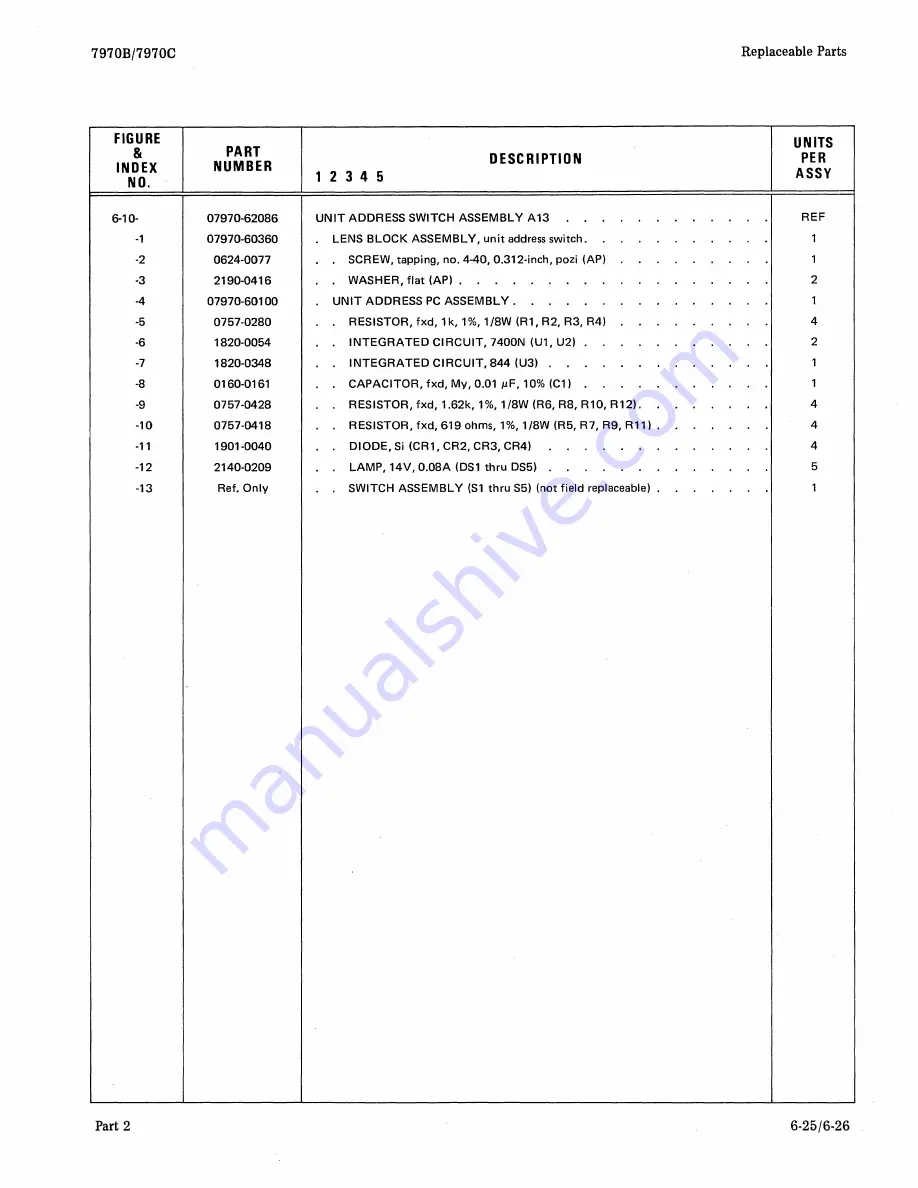
Страница 55: ...Replaceable Parts 7970B 7970C _ _ 4 SEE DETAIL A 4 5 6 6 11 11 11 11 13 797o 0S4A Figure 6 10 Unit Address Switch Assembly A13 6 24 Part 2 ...

Страница 56: ...7970 601 00 UNIT ADDRESS PC ASSEMBLY 1 5 0757 0280 RESISTOR fxd 1k 1 1 8W R1 R2 R3 R4 4 6 1820 0054 INTEGRATED CIRCUIT 7400N U1 U2 2 7 1820 0348 INTEGRATED CIRCUIT 844 U3 1 8 0160 0161 CAPACITOR fxd My 0 01 J lF 10 C1 1 9 0757 0428 RESISTOR fxd 1 62k 1 1 8W R6 R8 R10 R12 4 10 0757 0418 RESISTOR fxd 619 ohms 1 1 8W R5 R7 R9 R11 4 11 1901 0040 DIODE Si CR1 CR2 CR3 CR4 4 12 2140 0209 LAMP 14V 0 08A D...

Страница 57: ......

Страница 58: ...7970Bj7970C 25 26 27 28 7970 519 Part 2 21 22 23 24 13 14 15 16 2 3 4 2 3 17 18 19 20 Figure 6 11 Transport Harness Assembly W2 Sheet 1 of 2 5 6 7 8 Replaceable Parts 2 3 4 5 6 7 8 9 10 11 12 6 27 ...

Страница 59: ...Replaceable Parts 29 30 31 32 33 34 35 36 7970 520 6 28 33 34 35 36 Figure 6 11 Transport Harness Assembly W2 Sheet 2 of 2 7970B 7970C Part 2 ...

Страница 60: ...AP read only units 1 2680 0101 SCREW no 10 32 0 438 inch pozi AP read write units 1 15 2190 0034 WASHER lock helical AP 1 16 2190 0453 WASHER Ootype AP 1 17 1400 0294 CLAMP cable 0 5 inch 2 18 2680 0099 SCREW no 10 32 0 375 inch pozi AP 1 19 2190 0034 WASHER lock helical AP 1 20 2190 0453 WASHER Ootype AP 1 21 1400 0293 CLAMP calbe 0 375 inch 1 22 2680 0099 SCREW no 10 32 0 375 inch pozi AP 1 23 2...

Страница 61: ......

Страница 62: ...7970B 7970C Replaceable Parts THIS PAGE LEFT BLANK INTENTIONALLY Part 2 6 31 ...

Страница 63: ...0C 10 3 13 10 38 3 10 35 16 27 33 32 31 28 HIDDENI 7970 387A Part 2 Replaceable Parts 25 43 00rn 8 1102 42 3 j 19 l D 0 Cc J 29 30 29 25 22 22 23 24 21 Figure 6 12 Capstan Servo PC Assembly A9 Sheet 1 of 2 6 31 ...

Страница 64: ...35 A55 to CAll A66 R22 06 3 A28 C24 A40 A58 A56 A41 A30 9 A69 A57 A43 I C28 C23 J CA20 C14 8 A18 8 R34 C26 A14 A67 A12 8 A70 A13 C30 A18 8 A63 A42 C16 All CA16 A61 C31 A76 A8 A75 J CR15 9 R19 R85 R25 CR18 R84 CR17 C15 R83 C29 R80 Cl0 CR14 05 R16 8 C18 8 R6 A45 C9 A59 A15 8 R5 C11 CA19 A52 8 A4 A21 Cl A82 C2 A81 R17 A46 A44 An A74 A79 A53 Al A78 C8 A3 R60 A2 C7 R9 A20 C3 C5 C6 C4 Figure 6 12 Capsta...

Страница 65: ...I II 8 g I Cl i I _ 8 1 I 46 l IG I p T 68 72 63 49 65 66 67 64 R t I ir 1 g I I 01 I t s fIJII n 1 h n II I _ p c J II I I 56 B c r I 57 I 51 I 51 I 51 L cJ 1 I 50 CJ CJ 8 1 P 49 CJ r o 8 I P 61 62 62 58 48 61 61 61 59 60 7970 388A Figure 6 12 Capstan Servo PC Assembly A9 Sheet 2 of 2 6 32 Part 2 ...

Страница 66: ... BREAKOCWN 6 2V DICOE SILICON 50 MA 30 WV DIOOE SILICON 50 MA 30 WV DIODE SILICON 50 MA 30 WV OIODE BREAKCCWN 6 2V OICDE SILICON 50 MA 30 WV DICDE SILICON 50 MA 30 WV OIOOE BREAKOOWN b BIV 5 OIOOE SILICON 50 MA 30 WV OIDDE SILICON 50 MA 30 WV OIODE SILICON 50 MA 30 WV DIODE SILICON 50 MA 30 WV OIOOE SILICON 50 MA 30 WV DIOOE SILICON 50 MA 3D WV DIODE SILICON 50 MA 30 WV DICOE SILICON 50 MA 30 WV D...

Страница 67: ...STOR fxd 464k 1 1 8W R25 1 18 0757 0463 RESISTOR fxd 82 5k 1 1 8W R45 1 19 0698 3153 RESISTOR fxd 3 83k 1 1 8W R52 R59 2 20 2100 2850 RESISTOR var 10k R53 R60 2 21 0757 0466 RESISTOR fxd 110k 1 1 8W R74 1 22 0698 3152 RESISTOR fxd 3 48k 1 1 8W R1 R2 2 23 0698 3202 RESISTOR fxd 1 74k 1 1 8W R3 1 24 0757 0465 RESISTOR fxd lOOk 1 1 8W R44 1 25 0683 1035 RESISTOR fxd 10k 1 4W R20 R23 2 26 0757 0290 RE...

Страница 68: ...M U 118 1 28480 0757 0443 R49 0757 0447 R FXD MET FLM 16 2K OHM U IIBW 28480 0757 0447 R50 0757 041B 4 R FXC MET FLM 619 OHM U 1I8W 28480 0757 0418 R51 0757 0418 R FXD MET FLM 619 OHM 1 1 8 28480 0757 0418 R52 0698 3153 2 R FXD MET FLM 3 83K OHM 1 1I8W 28480 0698 3153 R53 21OC 2850 2 R VAR W 10K OHM 10 lW 28480 2100 2850 R54 0757 0279 1 R FXO MET FLM 3 16K OHM U 1I8W 28480 0757 0279 R55 0757 0424 ...

Страница 69: ...2N3904 08 09 012 013 4 57 0160 2250 CAPACITOR fxd cer 5 pF C18 1 58 0160 2207 CAPACITOR fxd mica 300 pF Cl1 1 59 07970 62025 DUMMY PLUG ASSEMBLY J6 1 60 0160 2414 CAPACITOR fxd My 0 0221LF C3 1 61 0150 0121 CAPACITOR fxd cer O lILF C4 C5 C6 C7 C8 5 62 0160 2151 CAPACITOR fxd My 0 011 ILF Cl C2 2 63 1854 0053 TRANSISTOR 2N2218 01 1 64 1853 0204 TRANSISTOR 2N4920 03 1 65 2200 0147 SCREW no 4 40 0 50...

Страница 70: ... 8 R52 R35 8 e R16 cr 012 8 R56 R57 8 D R48 R60 1 11 CR2 8 R59 1 11 CRll R42 8 R46 R58 R109 011 Kl cr u 09 R100 1 11 CRl R53 0 R4 cr R40 R6 C3 R3g RS u R50 I u R61 CR8 R3 C R51 cr Q R7 8 C4 R44 8 C2 R10S R19 J R15 cs Rl R2 I Cl I R17 R14 CR3 C7 G R13 IThm 07970 62173 l C8 C 1329 22 R12 RlO Rll 8 2040V TP R54 R8 7970 62173A Figure 6 13 Reel Servo PC Assembly A7 Sheet 1 of 2 Part 2 6 35 ...

Страница 71: ...7970B 7970C Replaceable Parts 7 6 19 1 17 16 2 2 5 5 4 8 5 9 18 7 6 7970 393A Figure 6 13 Reel Servo PC Assembly A7 Sheet 1 of 2 Part 2 6 35 ...

Страница 72: ...R62 R52 R35 8 a R16 cr R26 8 R56 R57 8 R48 a R60 1 11 CR2 u u 8 R59 1 11 CRll R42 8 R46 R58 Rl09 Qll Kl a u Q9 Rl00 1 11 CRl R53 a R40 R4 a R6 C3 R39 R5 s N u R50 f u R6l CR8 R3 0 a R5l R7 8 C4 R44 8 C2 R105 R19 R15 l C5 Rl Q3 R2 f 12 Cl I R17 R14 CR3 C7 G R13 Inm 07970 62173 19 C8 C 1321 22 R12 R10 Rll 8 12040V TP R54 R8 7970 G2173A Figure 6 13 Reel Servo PC Assembly A7 Sheet 2 of 2 6 36 Part 2 ...

Страница 73: ...Replaceable Parts 41 42 43 44 7970 394A 6 36 7970Bj7970C Figure 6 13 Reel Servo PC Assembly A7 Sheet 2 of 2 Part 2 ...

Страница 74: ...1015 Resistor Fxd Comp 100 ohms 5 1 4W 01121 CB1015 R7 26 0757 0797 Resistor Fxd Flm 90 9 ohms 1 1 2W 28480 0757 0797 R8 27 0698 3637 Resistor Fxd Ox 820 ohms 5 2W 28480 0698 3637 R9 10 15 28 29 0683 1025 Resistor Fxd Comp 1000 ohms 5 1 4W 01121 CB1025 34 100 101 R11 13 30 32 0761 0058 Resistor Fxd Met Ox 750 ohms 5 1W 28480 0761 0058 R12 31 0757 0401 Resistor Fxd Flm 100 ohms 1 1 8W 28480 0757 04...

Страница 75: ...8 RESISTOR fxd 100 ohms 1 2W R18 R37 2 17 0757 0797 RESISTOR fxd 90 9 ohms 1 2W R7 R26 2 18 0775 0199 RESISTOR fxd 21 5k 1 1 8W R50 1 19 0811 2048 RESISTOR fxd 0 25 ohm 25W R40 R42 2 20 0160 0153 CAPACITOR fxd 0 001 J IF My C7 C8 C18 C19 4 21 1854 0022 TRANSISTOR NPN Si 2N2102 01 05 2 22 1855 0052 TRANSISTOR field effect 2N4360 014 015 2 23 1853 0080 TRANSISTOR 2N4888 02 06 2 24 0160 2055 CAPACITO...

Страница 76: ......

Страница 77: ... pozi AP 1 43 3050 0105 WASHER flat AP 1 44 2260 0009 NUT hex no 4 40 AP 1 45 0160 0165 CAPACITOR fxd 0 056J LF My C9 C20 2 46 1854 0490 TRANSISTOR NPN Si 2N3773 09 010 011 012 4 47 2200 0145 SCREW no 4 40 0 438 inch pozi AP 2 48 3050 0105 WASHER flat AP 2 49 2260 0009 NUT no 4 40 AP 2 50 0160 2128 CAPACITOR fxd 0 33 J LF C23 C24 2 51 1901 0364 DIODE ASSEMBLY Si CR6 1 6 38 Part 2 ...

Страница 78: ...17970C Part 2 1 2 3 4 5 6 6 11 12 13 56 _ _ 32 6 27 27 42 c J F r 11 c J r 9 10 26 41 40 39 35 34 34 33 20 22 32 31 30 20 36 37 38 Figure 6 14 Power Regulator PC Assembly A21 Replaceable Parts 7970 066C 6 39 ...

Страница 79: ...17970C Part 2 51 52 53 32 6 27 27 42 1 2 3 4 41 5 6 6 40 39 35 34 34 33 20 22 32 31 36 37 3B Figure 6 14_ Power Regulator PC Assembly A21 30 20 11 12 13 13 14 14 15 28 29 26 Replaceable Parts 7970 066C 6 39 ...

Страница 80: ... 5 1 2W R18l 1 19 1853 0036 TRANSISTOR PNP Si 2N3906 08 018 2 20 1820 0439 INTEGRATED CIRCUIT voltage regulator Ul U2 U3 3 21 1853 0027 TRANSISTOR PNP Si 2N3245 09 1 22 0698 3150 RESISTOR fxd 2 37k 1 1 8W R2 R26 2 23 1854 0039 TRANSISTOR NPN Si EIA 2N3053 01 014 2 24 1902 0049 DIODE zener 6 19V CR16 1 25 1902 2303 DIODE zener 14 7V CR15 1 26 0698 3438 RESISTOR fxd 147 ohms 1 l 8W Rl R25 2 27 0757 ...

Страница 81: ... R18 1 19 1853 0036 TRANSISTOR PNP Si 2N3906 08 Q9 Q18 3 20 1820 0439 INTEGRATED CIRCUIT voltage regulator Ul U2 U3 3 21 0757 0441 RESISTOR fxd 8 25k 1 1 8W R16 1 22 0698 3150 RESISTOR fxd 2 37k 1 1 8W R2 R26 2 23 1854 0039 TRANSISTOR NPN Si EIA 2N3053 Ql Q14 2 24 0340 0164 INSULATOR transistor 1 25 0757 0440 RESISTOR fxd 7 5k l l 8W R17 1 26 0698 3438 RESISTOR fxd 147 ohms 1 l 8W R1 R25 2 27 0757...

Страница 82: ...TOR fxd 51 1 k 1 1 8W R37 1 49 0757 0458 RESISTOR fxd 51 1 k 1 1 8W R38 1 50 0757 0419 RESISTOR fxd 681 ohms 1 1 8W R39 1 51 1853 0052 TRANSISTOR PNP Si 2N3740 06 1 52 0340 0180 INSULATOR transistor mica 1 53 2360 0195 SCREW no 6 32 0 312 inch pozi 2 54 2420 0001 NUT hex no 6 32 0 312 inch 2 55 0160 2055 CAPACITOR fxd 0 01 LF 100 Vdcw C2 C4 2 56 1854 0022 TRANSISTOR NPN Si 05 1 57 1902 3311 DIODE ...

Страница 83: ... 1 48 0757 0199 RESISTOR fxd 21 5k 1 1 8W R37 1 49 0698 3157 RESISTOR fxd 19 6k 1 1 8W R38 1 50 0757 0419 RESISTOR fxd 681 ohms 1 1 8W R39 1 51 1853 0052 TRANSISTOR PNP Si 2N3740 Q6 1 52 0340 0180 INSULATOR transistor mica 1 53 2360 0195 SCREW no 6 32 0 312 inch pozi 2 54 2420 0001 NUT hex no 6 32 0 312 inch 2 55 0160 2055 CAPACITOR fxd 0 01 IF 100 Vdcw C2 C4 2 56 1854 0022 TRANSISTOR NPN Si Q5 1 ...

Страница 84: ...Replaceable Parts 7970Bj7970C 7970 C 067 Figure 6 15 Power Distribution Assembly A20 6 42 Part 2 ...

Страница 85: ...1 2180 RESISTOR fxd wW 12k 5 5W Rl R21 2 13 2200 0141 SCREW no 4 40 0 312 inch pozi AP 2 14 2190 0071 WASHER lock AP 2 15 0160 2149 CLAMP capacitor 3 16 2360 0201 SCREW no 6 32 0 500 inch pozi AP 1 17 2420 0001 NUT hex no 6 32 AP 1 18 2200 0143 SCREW no 4 40 0 375 inch pozi AP 2 19 2190 0003 WASHER lock helical AP 2 20 3050 0105 WASHER brass AP 2 21 0180 1970 CLAMP capacitor 2 22 2360 0201 SCREW n...

Страница 86: ...Replaceable Parts 21 8 21 6 6 44 18 19 20 8 10 10 11 8 7970B 7970C 12 12 __ t 7 1 21 1 6 I 14 15 16 17 13 Figure 6 16 Power Distribution PC Assembly I I _ 15 16 17 7970 068A Part 2 ...

Страница 87: ...0104 CAPACITOR fxd 200 uF 15 Vdcw C6 C7 C8 3 9 0812 0045 RESISTOR fxd WW 0 15 ohm 5 3W R6 1 10 0811 0666 RESISTOR fxd WW 1 ohm 5 2W R7 R8 2 11 0811 1665 RESISTOR fxd WW 0 56 ohm 5 2W R9 1 12 1901 0630 DIODE Si CR1 CR2 2 13 2110 0303 FUSE slo blo 2A 250V Fl F41 2 14 0764 0043 RESISTOR fxd 2 7k 5 2W R4 R5 2 15 0180 2325 CAPACITOR fxd 1500 uF 75 Vdcw C4 C5 2 16 2680 0128 SCREW no 10 32 0 25 inch pozi...

Страница 88: ...Replaceable Parts 7970B 7970C 31 It 30 29 28 3 4 12 34 7970 C 069A 17 former Assembly A19 Figure 6 17 Trans 6 46 Part 2 ...

Страница 89: ...ridge rectifier CR3 1 15 2200 0151 SCREW no 4 40 0 750 inch pozi AP 2 16 2190 0061 WASHER lock helical AP 2 17 2110 0365 FUSE slo blo 4A 250V F1 1 18 2110 0303 FUSE slo blo 2A 250V F2 1 19 1400 0084 FUSEHOLDER 3 AG fuse extractor post type XF1 XF2 2 20 0360 1590 TERMI NAL STRIP lug type TB1 1 21 2200 0139 SCREW no 4 40 0 250 inch pozi AP 1 22 2190 0061 WASHER lock helical AP 1 23 0360 0043 TERMINA...

Страница 90: ......

Страница 91: ...7970B 7970C Part 2 6 2 2 2 2 r T _ _ 5 2 4 3 2 Figure 6 18 Control and Status PC Assembly A16 Sheet 1 of 2 Replaceable Parts 2 7970 A 72 6 49 ...

Страница 92: ...laceable Parts 13 14 18 13 13 24 6 50 15 15 15 15 16 17 23 15 14 23 15 7970B 7970C 17 18 15 15 14 19 20 16 18 lLi 18 21 21 22 15 7970 A 73 Figure 6 18 Control and Status PC Assembly A16 Sheet 2 of 2 Part 2 ...

Страница 93: ...757 0442 RESISTOR fxd 10k 1 1 BW R26 1 9 0698 3161 RESISTOR fxd 38 3k 1 1 BW R22 1 10 069B 3162 RESISTOR fxd 46 4k 1 1 8W R20 1 11 069B 3446 RESISTOR fxd 383 ohms 1 1 BW R16 R25 2 12 0757 0401 RESISTOR fxd 100 ohms 1 1 8W R15 1 13 1901 0040 DIODE Si CR2 thru CR11 CR100 11 14 1B20 0054 INTEGRATED CIRCUIT type 7400N U1 U4 U14 U16 U19 U21 6 15 0160 2055 CAPACITOR fxd 0 01 LF C1 C2 C4 C6 thru C17 13 1...

Страница 94: ...90201 CGS152U075B03L 0757 0199 28480 0757 0199 0180 2326 90201 CGS103U015B03L 0757 0278 28480 0757 0278 0180 2327 90201 CGS243U030E 03L 0757 0280 28480 0757 0280 0340 0164 28480 0340 0164 0757 0289 28480 0757 0289 0340 0180 28480 0340 0180 0757 0290 28480 0757 0290 0360 0043 00000 aBO 0757 0317 28480 0757 0317 0360 0124 28480 0360 0124 0757 0401 28480 0757 0401 0360 1590 71785 SPECIAL aBO 0757 041...

Страница 95: ...aBO 1853 0036 80131 2N3906 2190 0417 00000 aBO 1853 0052 80131 2N3740 2190 0420 00000 aBO 1853 0080 80131 2N4888 2190 0429 00000 aBO 1853 0204 80131 2N4920 2190 0432 00000 aBO 1854 0022 07263 S17843 2190 0451 95987 06 128 1854 0039 80131 2N3053 2190 0452 95987 06 140 1854 0045 04713 2N956 2190 0453 95987 06 191 1854 0053 80131 2N2218 2190 0475 08289 NY l0 030 1854 0063 80131 2N3055 2190 0483 00000...

Страница 96: ...4 9006 2190 0032 3030 0038 2190 0034 28480 2190 0034 3030 0047 0000 aBO 2190 0040 00000 aBO 3030 0196 00000 aBO 2190 0061 00000 aBO 3030 0310 0000 aBO 2190 0071 78189 1804 00 3030 0329 0000 aBO 2190 0085 00000 aBO 3030 0401 0000 aBO 2190 0102 28480 2190 0102 3030 0425 0000 aBO 2190 0149 00000 aBO 3050 0002 00000 aBO 2190 0181 00000 aBO 3050 0016 00000 aBO 2190 0312 00000 aBO 3050 0032 00000 aBO 21...

Страница 97: ...j7970C SECTION VII MAINTENANCE DIAGRAMS Maintenance Diagrams This section contains schematic and parts location diagrams for the tape transport of the HP 7970B 7970C Digital Magnetic Tape Unit Part 2 7 117 2 ...

Страница 98: ......

Страница 99: ......

Страница 100: ......

Страница 101: ......

Страница 102: ......

Страница 103: ... K R3 I R36 I SUPPLY A PL R33 10K R45 R47 10K 13 3K R I 06 2K R48 1 78K al5 era G 014 R49 R42 100K 121 25 R51 II2II2IK 7 KIA 4 20 40V i PIO CR6 7 J 6 I I I I I I I I I I I I I I I I I I R5 R6 ____________ _ D L C __4 __ J5 I I 12V R4 10 3BPf 7 C4 30PF 348K 348K RI04 RI6 2K R53 I r8K RI05 R40 21 25 I I I I I 20 40V I K 2 14 V R 75 31IK Q3 R44 QI6 01 Q IJ 3K CD r L WHT BlK CRN 1 i w C5 2 n J3 r_ _ _...

Страница 104: ......

Страница 105: ......

Страница 106: ......

Отзывы:

Похожие инструкции для 7970B