b.
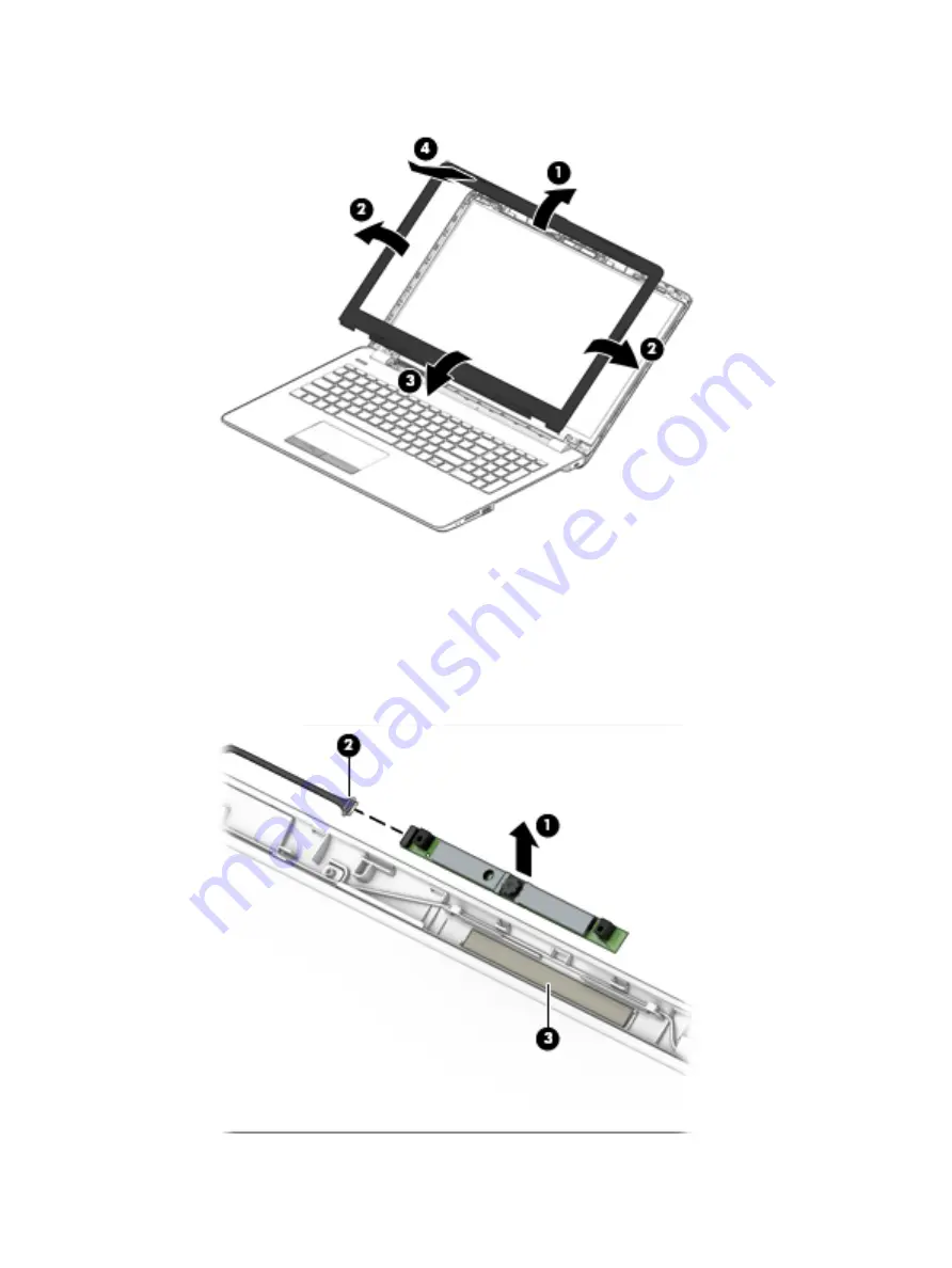
Remove the display bezel (4).
3.
To remove the camera/microphone module:
a.
Position the display assembly with the top edge toward you.
b.
Pry up to disengage the camera/microphone module from the adhesive that secures it to the
display (1).
c.
Disconnect the cable (2) from the module.
d.
Remove the tape from the enclosure (3). Replacement cameras come with tape already installed.
36
Chapter 6 Removal and replacement procedures for Authorized Service Provider parts
Содержание 250 G6
Страница 1: ...HP 250 G6 Notebook PC Maintenance and Service Guide ...
Страница 4: ...iv Safety warning notice ...
Страница 8: ...viii ...
Страница 13: ...Category Description 7th gen Dis 7th gen UMA 6th gen Dis 6th gen UMA Pen Cel UMA Battery Optical drive 5 ...
Страница 14: ...6 Chapter 1 Product description ...
Страница 26: ...18 Chapter 2 Components ...
Страница 88: ...80 Chapter 6 Removal and replacement procedures for Authorized Service Provider parts ...
Страница 106: ...98 Chapter 10 Specifications ...
Страница 116: ...108 Chapter 12 Power cord set requirements ...
Страница 118: ...110 Chapter 13 Recycling ...


