background image

Power connector cable

Table 6-5

  Power connector cable description and part number

Description

Spare part number

Power connector cable

L57017-001

Before removing the power connector cable, follow these steps:

1.

Prepare the computer for disassembly (

Preparation for disassembly on page 26

).

2.

Remove the bottom cover (see 

Bottom cover on page 27

).

3.

Disconnect the battery (see 

Battery and speakers on page 32

).

4.

Remove the heat sink/fan assembly (see 

Heat sink/fan assembly on page 35

).

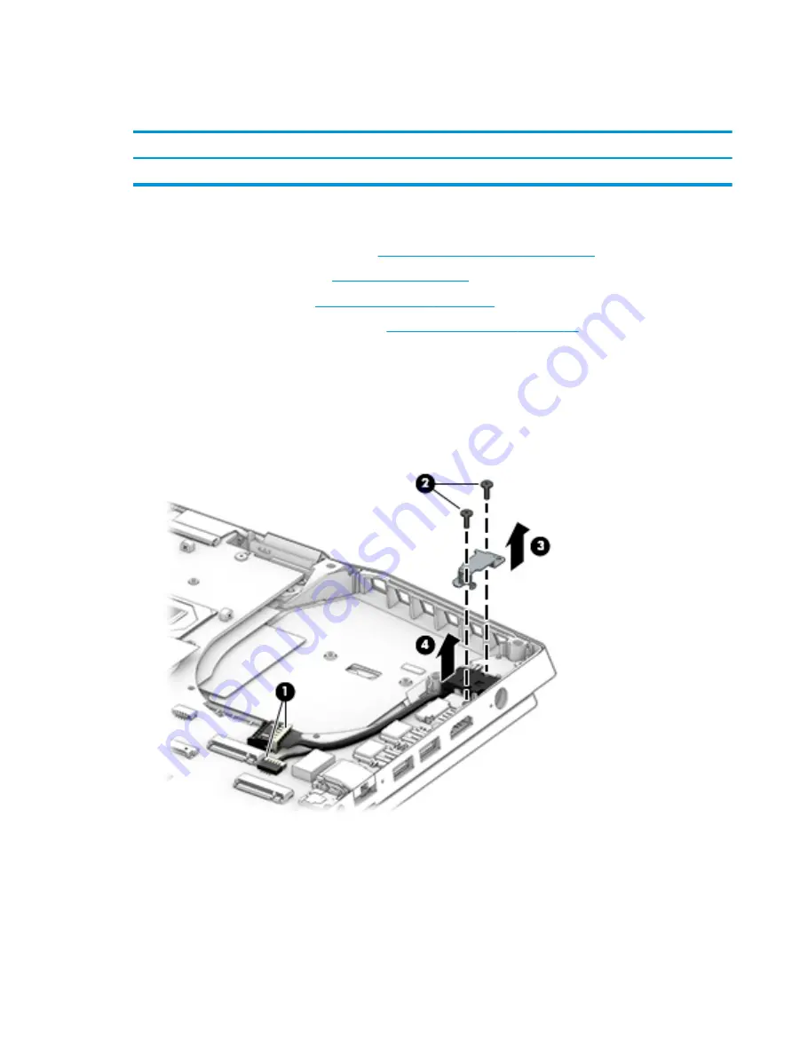
Remove the power connector cable:

1.

Disconnect the cable from the system board (1).

2.

Remove the two Phillips M2.0 × 5.5 screws (2) that secure the bracket to the computer, and then remove 
the bracket (3).

3.

Remove the power connector and cable from the computer (4).

Reverse this procedure to install the power connector cable.

Component replacement procedures

39

Содержание 15-dq0000

Страница 1: ...Maintenance and Service Guide OMEN X by HP 15 Laptop PC ...

Страница 2: ...ein First Edition May 2019 Document Part Number L64223 001 Product notice This guide describes features that are common to most models Some features may not be available on your computer Not all features are available in all editions or versions of Windows Systems may require upgraded and or separately purchased hardware drivers software or BIOS update to take full advantage of Windows functionali...

Страница 3: ...ts that should be accessed by only an authorized service provider See Chapter 5 Removal and replacement procedures for Customer Self Repair parts for details Accessing parts described in Chapter 6 Removal and replacement procedures for authorized service provider parts can damage the computer or void your warranty iii ...

Страница 4: ...iv Important Notice about Customer Self Repair Parts ...

Страница 5: ...hard flat surface Do not allow another hard surface such as an adjoining optional printer or a soft surface such as pillows or rugs or clothing to block airflow Also do not allow the AC adapter to contact the skin or a soft surface such as pillows or rugs or clothing during operation The device and the AC adapter comply with the user accessible surface temperature limits defined by applicable safe...

Страница 6: ...vi Safety warning notice ...

Страница 7: ...bles 18 Display assembly subcomponents 19 Miscellaneous parts 20 4 Removal and replacement procedures preliminary requirements 21 Tools required 21 Service considerations 21 Plastic parts 21 Cables and connectors 21 Drive handling 22 Workstation guidelines 22 Electrostatic discharge information 22 Generating static electricity 23 Preventing electrostatic damage to equipment 23 Personal grounding m...

Страница 8: ...rd 46 Touchpad cable 47 Second display panel 48 Display assembly 51 Keyboard top cover 59 7 Using Setup Utility BIOS 60 Starting Setup Utility BIOS 60 Updating Setup Utility BIOS 60 Determining the BIOS version 60 Downloading a BIOS update 61 8 Using HP PC Hardware Diagnostics 62 Using HP PC Hardware Diagnostics Windows select products only 62 Downloading HP PC Hardware Diagnostics Windows 62 Down...

Страница 9: ...roduct name or number 65 Customizing Remote HP PC Hardware Diagnostics UEFI settings 65 9 Backing up restoring and recovering 67 Backing up information and creating recovery media 67 Using Windows tools 67 Using the HP Cloud Recovery Download Tool to create recovery media select products only 67 Restoring and recovery 68 Restoring resetting and refreshing using Windows tools 68 Recovering using HP...

Страница 10: ...x ...

Страница 11: ...c internal and external Supports VR Supports second screen via DisplayPort output with HDCP 2 2 capability Display panel Primary display 16 9 Ultra Wide Aspect Ratio 15 6 in full high definition FHD 1920 1080 WLED UWVA antiglare uslim III flat 2 6 mm narrow bezel 300 nits G Sync supportable 240 Hz display sRGB eDP 1 4 PSR 144 Hz display eDP 1 4 PSR2 15 6 in ultra high definition UHD 3840 2160 WLED...

Страница 12: ...2 2 Audio Audio brand BANG OLUFSEN Audio control panel OMEN Audio Control Supports HP Audio Boost 2 0 with discrete amplifier Support DTS X Ultra Stereo speakers Video HP Wide Vision FHD Camera indicator LED USB 2 0 HD BSI sensor f2 2 WDR 88 WFOV 1080p by 30 frames per second Dual array digital microphone with appropriate software beam forming echo cancellation noise suppression RJ 45 network jack...

Страница 13: ...2 HP Sleep Charge Internal card expansion Two M 2 slots for solid state drive Keyboard pointing devices Keyboard Full sized backlit Dura coat island style keyboard Supports RGB per key lighting adjustable via OMEN Command Center Supports All Key NKRO Touchpad requirements ClickPad with image sensor Multitouch gestures enabled Support for Precision Touchpad Support for modern trackpad gestures Taps...

Страница 14: ...0 Home 64 Plus Single Language Africa Market PPP Windows 10 Home 64 Plus Single Language India Market PPP Windows 10 Home 64 Plus Single Language Indonesia Market PPP Windows 10 Pro 64 Windows 10 Pro 64 Web Kiosk FreeDOS 3 0 Serviceability End user replaceable parts AC adapter Memory modules Solid state drive 4 Chapter 1 Product description ...

Страница 15: ... USB devices that have a Type C connector such as a cell phone camera activity tracker or smartwatch and provides high speed data transfer and Connects a display device that has a USB Type C connector providing DisplayPort output NOTE Your computer may also support a Thunderbolt docking station NOTE Cables and or adapters purchased separately may be required 2 USB SuperSpeed port with HP Sleep and...

Страница 16: ...ven when the computer is off charge most products such as a cell phone camera activity tracker or smartwatch 5 RJ 45 network jack status lights Connects a network cable White The network is connected Amber Activity is occurring on the network 6 Audio out headphone Audio in microphone combo jack Connects optional powered stereo speakers headphones earbuds a headset or a television audio cable Also ...

Страница 17: ...ial recognition logon to Windows instead of a password logon NOTE Camera functions vary depending on the camera hardware and software installed on your product The antennas are not visible from the outside of the computer For optimal transmission keep the areas immediately around the antennas free from obstructions For wireless regulatory notices see the section of the Regulatory Safety and Enviro...

Страница 18: ...ption 1 Touchpad zone Reads your finger gestures to move the pointer or activate items on the screen 2 Left touchpad button Functions like the left button on an external mouse 3 Right touchpad button Functions like the right button on an external mouse 8 Chapter 2 Getting to know your computer ...

Страница 19: ...ibernation Hibernation is a power saving state that uses the least amount of power 2 Caps lock light On Caps lock is on which switches the key input to all capital letters 3 Mute light On Computer sound is off Off Computer sound is on 4 Windows lock key light On The Windows key is disabled Off The Windows key is enabled 5 Second screen touch gestures light On The touch gestures on the second scree...

Страница 20: ...essing and holding down the power button results in the loss of unsaved information If the computer has stopped responding and shutdown procedures are ineffective press and hold the power button down for at least 5 seconds to turn off the computer To learn more about your power settings see your power options Right click the Power icon and then select Power Options 2 Second screen Offers multiple ...

Страница 21: ...y 5 OMEN key Opens the OMEN Command Center software See HP OMEN Command Center on page 14 for more information 6 Virtual numeric keypad key Displays a virtual numeric keypad on the second screen The virtual numeric keypad can be used like an external numeric keypad Press the key again to turn off the numeric keypad 7 Second screen backlight key Turns the second screen backlight on and off 8 Second...

Страница 22: ...nables airflow to cool internal components NOTE The computer fan starts up automatically to cool internal components and prevent overheating It is normal for the internal fan to cycle on and off during routine operation 2 Speakers 2 Produce sound 12 Chapter 2 Getting to know your computer ...

Страница 23: ...in this section the bottom of the computer inside the battery bay under the service door on the back of the display or on the bottom of a tablet kickstand Service label Provides important information to identify your computer When contacting support you may be asked for the serial number the product number or the model number Locate this information before you contact support Table 2 9 Service lab...

Страница 24: ...a central location to access and configure the following features NOTE Some features are available on select products only System Vitals Monitor the computer status and performance Overclocking Enhance your gaming performance with Memory Turbo Mode Lighting Customize the keyboard and OMEN logo lighting select products only Real time screen mirroring Display and interact with a portion of your game...

Страница 25: ... Display OMEN Command Center and view system vitals and make changes Open additional applications View the virtual numeric keypad To navigate the second screen Touch the second screen directly using touch gestures NOTE To turn the second screen touch gestures off and on press fn f12 To move content between the main screen and the second screen Select the content and press the screen switch key or ...

Страница 26: ...rted parts for your computer go to http partsurfer hp com select your country or region and then follow the on screen instructions NOTE Details about your computer including model serial number product key and length of warranty are on the service tag at the bottom of your computer See Labels on page 13 for details 16 Chapter 3 Illustrated parts catalog ...

Страница 27: ...001 4 Heat sink fan assembly L57018 001 5 Battery 6 cell 72 Wh L32749 005 6 Speakers L57030 001 7 Power button board NOTE The power button board cable is available as spare part number L57012 001 L57020 001 8 Power connector cable L57017 001 9 IR sensor board NOTE The IR sensor board cable is available as spare part number L57013 001 L57021 001 10 Second display transfer board NOTE The second disp...

Страница 28: ...2080 L57038 601 Intel Core i7 9750H processor and 8 GB of discrete graphics memory GeForce GTX 2070 L57036 601 15 Second display L57028 001 16 Bottom cover includes thermal pad L57010 001 Cables Table 3 2 Cables and their descriptions Item Component Spare part number 1 Power button board cable L57012 001 2 IR sensor board cable L57013 001 3 Touchpad cable L57014 001 4 Display transfer board cable ...

Страница 29: ...umber L57048 001 L57011 001 2 Display panel includes display panel and bezel adhesives UHD 60 Hz 550 nits L57025 001 UHD 60 Hz 340 nits L57026 001 FHD 240 Hz 300 nits L62861 001 FHD 144 Hz 300 nits L57024 001 3 Display panel cable includes display panel and bezel adhesives L57016 001 4 Webcam microphone module includes double sided adhesive L57040 001 Display assembly subcomponents 19 ...

Страница 30: ...r descriptions Component Spare part number AC adapter 230 W PFC slim 7 4 mm 925141 850 Power cord C13 1 0 m For use in Australia L63248 001 For use in Denmark L63249 001 For use in Europe L63250 001 For use in India L63252 001 For use in Israel L63251 001 For use in Italy L64040 001 For use in Japan L63253 001 For use in North America L63255 001 For use in the People s Republic of China L63256 001...

Страница 31: ...mage Plastic parts IMPORTANT Using excessive force during disassembly and reassembly can damage plastic parts Cables and connectors IMPORTANT When servicing the computer be sure that cables are placed in their proper locations during the reassembly process Improper cable placement can damage the computer Cables must be handled with extreme care to avoid damage Apply only the tension required to un...

Страница 32: ...with approved static shielding material Use a wrist strap connected to a properly grounded work surface and use properly grounded tools and equipment Use conductive field service tools such as cutters screw drivers and vacuums When fixtures must directly contact dissipative surfaces use fixtures made only of static safe materials Keep the work area free of nonconductive materials such as ordinary ...

Страница 33: ...000 V 6 000 V 2 000 V Removing DIPs from vinyl tray Removing DIPs from Styrofoam Removing bubble pack from PCB Packing PCBs in foam lined box 2 000 V 3 500 V 7 000 V 5 000 V 4 000 V 5 000 V 20 000 V 11 000 V 11 500 V 14 500 V 26 500 V 21 000 V Electronic components can be packaged together in plastic tubes trays or Styrofoam NOTE As little as 700 volts can degrade a product Preventing electrostati...

Страница 34: ... work area take the following precautions Cover the work surface with approved static dissipative material Provide a wrist strap connected to the work surface and properly grounded tools and equipment Use static dissipative mats foot straps or air ionizers to give added protection Handle electrostatic sensitive components parts and assemblies by the case or PCB laminate Handle them only at static ...

Страница 35: ... with conductive or approved containers or packaging Keep ESD sensitive parts in their containers until the parts arrive at static free workstations Place items on a grounded surface before removing items from their containers Always be properly grounded when touching a component or assembly Store reusable ESD sensitive parts from assemblies in protective packaging or nonconductive foam Use transp...

Страница 36: ...r complete and current information on supported parts for your computer go to http partsurfer hp com select your country or region and then follow the on screen instructions There are as many as 7 screws that must be removed replaced and or loosened when servicing Customer Self Repair parts Make special note of each screw size and location during removal and replacement Preparation for disassembly...

Страница 37: ...repare the computer for disassembly Preparation for disassembly on page 26 Remove the bottom cover 1 Loosen the two Torx T6 2 0 2 0 screws 1 from the bottom corners of the bottom cover 2 Loosen the four Torx T6 2 5 4 0 screws 2 from along the top edge of the bottom cover 3 At the gap in the hinge use a tool to loosen the bottom cover from the computer 1 Component replacement procedures 27 ...

Страница 38: ...ottom cover to separate it from the computer 2 and then remove the bottom cover from the computer 3 Reverse this procedure to install the bottom cover 28 Chapter 5 Removal and replacement procedures for Customer Self Repair parts ...

Страница 39: ...32 001 Before removing the solid state drive follow these steps 1 Prepare the computer for disassembly Preparation for disassembly on page 26 2 Remove the bottom cover see Bottom cover on page 27 3 Disconnect the battery see Battery and speakers on page 32 Remove the solid state drive Remove the Phillips M2 0 2 0 screw 1 and then pull the drive from the socket 2 Reverse this procedure to install t...

Страница 40: ...y modules 1 Spread the two retention clips outward 1 until the memory module tilts up at a 45 degree angle NOTE Do not completely remove the protective sheet from the primary memory module 2 Grasp the edge of the memory module 2 and then gently pull the module out of the slot Use the same procedure to remove both memory modules IMPORTANT To prevent damage to the memory module hold the memory modul...

Страница 41: ...rews that must be removed replaced or loosened when servicing the computer Make special note of each screw size and location during removal and replacement Thermal material Table 6 1 Thermal material description and part number Description Spare part number Liquid metal thermal material L65923 001 Thermal material must be applied on site and therefore is not included in component spare part kits W...

Страница 42: ... the computer for disassembly Preparation for disassembly on page 26 2 Remove the bottom cover see Bottom cover on page 27 Remove the battery and speakers 1 Disconnect the battery cable from the system board 2 Disconnect the speaker cable from the system board 1 3 Remove the four Phillips M2 0 4 8 screws 2 that secure the speakers to the computer 32 Chapter 6 Removal and replacement procedures for...

Страница 43: ...4 Remove the two Phillips M2 5 5 5 screws 3 that secure the battery from the computer Component replacement procedures 33 ...

Страница 44: ...routing channel 3 for the speaker cable Make sure the cable is routed correctly when reinstalling the battery and speakers Reverse this procedure to install the battery and speakers 34 Chapter 6 Removal and replacement procedures for authorized service provider parts ...

Страница 45: ...ion for disassembly on page 26 2 Remove the bottom cover see Bottom cover on page 27 3 Disconnect the battery see Battery and speakers on page 32 Remove the heat sink fan assembly 1 Remove the two Phillips M2 0 2 5 screws 1 that secure the bracket to the computer 2 Remove the bracket from the fan 2 3 Disconnect the two fan cables from the system board 1 4 Remove the three Phillips M2 0 5 5 screws ...

Страница 46: ... removing any part that also requires removal of the heat sink be sure to order and apply thermal material Apply liquid metal to the integrated processor on the system board 1 IMPORTANT Be sure to completely cover the surface of the processor with liquid metal Failure to do so may cause reduced heat dissipation and lead to the computer overheating Only apply a thin layer of liquid metal over the e...

Страница 47: ...Reverse this procedure to install the heat sink fan assembly Component replacement procedures 37 ...

Страница 48: ...sfer board follow these steps 1 Prepare the computer for disassembly Preparation for disassembly on page 26 2 Remove the bottom cover see Bottom cover on page 27 3 Disconnect the battery see Battery and speakers on page 32 Remove the second display transfer board 1 Disconnect the cable from the ZIF connector on the second display transfer board 1 2 Remove the two Phillips M2 0 2 5 screws 2 that se...

Страница 49: ...see Bottom cover on page 27 3 Disconnect the battery see Battery and speakers on page 32 4 Remove the heat sink fan assembly see Heat sink fan assembly on page 35 Remove the power connector cable 1 Disconnect the cable from the system board 1 2 Remove the two Phillips M2 0 5 5 screws 2 that secure the bracket to the computer and then remove the bracket 3 3 Remove the power connector and cable from...

Страница 50: ...omputer for disassembly Preparation for disassembly on page 26 2 Remove the bottom cover see Bottom cover on page 27 3 Disconnect the battery see Battery and speakers on page 32 4 Remove the fan heat sink assembly see Heat sink fan assembly on page 35 Remove the power button board 1 Disconnect the cable from the ZIF connector on the power button board 1 2 Remove the Phillips M2 0 3 0 screw 2 that ...

Страница 51: ...teps 1 Prepare the computer for disassembly Preparation for disassembly on page 26 2 Remove the bottom cover see Bottom cover on page 27 3 Remove the battery and speakers see Battery and speakers on page 32 4 Remove the solid state drive see Solid state drive and Optane Memory Module on page 29 5 Remove the heat sink fan assembly see Heat sink fan assembly on page 35 6 Remove the second display tr...

Страница 52: ...board to the computer 3 Lift the left side of the system board 2 4 Rotate the system board upside down 1 and then disconnect the keyboard cable from the ZIF connector on the keyboard 2 42 Chapter 6 Removal and replacement procedures for authorized service provider parts ...

Страница 53: ...5 Remove the system board from the computer 3 Reverse this procedure to install the system board Component replacement procedures 43 ...

Страница 54: ...olid state drive and Optane Memory Module on page 29 5 Remove the heat sink fan assembly see Heat sink fan assembly on page 35 6 Remove the second display transfer board see Second display transfer board on page 38 7 Remove the power connector board and bracket see Power connector cable on page 39 8 Remove the system board see System board on page 41 Remove the network connector door From the remo...

Страница 55: ... and Optane Memory Module on page 29 5 Remove the heat sink fan assembly see Heat sink fan assembly on page 35 6 Remove the second display transfer board see Second display transfer board on page 38 7 Remove the power connector board and bracket see Power connector cable on page 39 8 Remove the system board see System board on page 41 Remove the thermal shield 1 Remove the Phillips M2 0 2 5 screw ...

Страница 56: ...e solid state drive see Solid state drive and Optane Memory Module on page 29 5 Remove the heat sink fan assembly see Heat sink fan assembly on page 35 6 Remove the second display transfer board see Second display transfer board on page 38 7 Remove the power connector board and bracket see Power connector cable on page 39 8 Remove the system board see System board on page 41 Remove the IR sensor b...

Страница 57: ...id state drive and Optane Memory Module on page 29 5 Remove the heat sink fan assembly see Heat sink fan assembly on page 35 6 Remove the second display transfer board see Second display transfer board on page 38 7 Remove the power connector board and bracket see Power connector cable on page 39 8 Remove the system board see System board on page 41 Remove the touchpad cable 1 Disconnect the cable ...

Страница 58: ...on page 32 4 Remove the solid state drive see Solid state drive and Optane Memory Module on page 29 5 Remove the heat sink fan assembly see Heat sink fan assembly on page 35 6 Remove the second display transfer board see Second display transfer board on page 38 7 Remove the power connector board and bracket see Power connector cable on page 39 8 Remove the system board see System board on page 41 ...

Страница 59: ... evenly IMPORTANT To avoid tearing the tape be sure to follow the order of the steps in this procedure 5 Pull the tape out from the top of the left side of the panel 3 6 Pull the tape out from the top of the right side of the panel 4 7 Pull the tape out from the bottom of the left side of the panel 5 8 Pull the tape out from the bottom of the right side of the panel 6 9 Pull the tape out from the ...

Страница 60: ...ieces of conductive tape 1 that secure the display to the computer 12 Push the display downward 2 and then rotate the display off the computer 3 Reverse this procedure to install the second display panel 50 Chapter 6 Removal and replacement procedures for authorized service provider parts ...

Страница 61: ...Power connector cable on page 39 7 Remove the system board see System board on page 41 Remove the display assembly 1 Remove the wireless antenna cables from the clips in the computer chassis 1 2 Remove the three Phillips M2 5 4 5 screws 2 from each hinge 3 Open the display to 90º 3 4 Separate the display from the computer 4 5 If it is necessary to replace display assembly subcomponents first remov...

Страница 62: ... part number L57048 001 6 If it is necessary to remove the hinge covers Pull the hinge covers straight up and off the display back cover The hinge covers are available as spare part number L66225 001 7 If it is necessary to remove the display panel 52 Chapter 6 Removal and replacement procedures for authorized service provider parts ...

Страница 63: ...the panel 2 IMPORTANT To avoid tearing the tape pull the tape evenly and carefully TIP You have to pull on the tape multiple times before it is completely removed c Lift the top of the panel up and rotate the panel over next to the display back cover 3 d Remove the tape from the connector on the back of the display panel 1 and then disconnect the cable from the panel 2 Component replacement proced...

Страница 64: ... for FHD 240 Hz 300 nit panel 8 If it is necessary to remove the webcam module Disconnect the cable from the module 1 and then lift evenly on both sides of the webcam to detach the it from the display back cover 2 The webcam module is attached to the display back cover with adhesive The webcam is available as spare part number L57040 001 54 Chapter 6 Removal and replacement procedures for authoriz...

Страница 65: ...ve the three Phillips M2 5 2 5 screws 1 from each hinge b Remove the hinges from the display back cover 2 The display hinges are available as spare part number L57019 001 c Remove the three Phillips M2 0 2 5 screws 1 from each bracket Component replacement procedures 55 ...

Страница 66: ...cable from the display backlight board at the bottom of the display back cover 1 and then remove the cable from the clip 2 b Peel the cable from the inside of the display back cover 3 The display cable is available as spare part number L57016 001 56 Chapter 6 Removal and replacement procedures for authorized service provider parts ...

Страница 67: ...module cable 2 from the board b Use a tool to remove the board from the display LED cover 3 The display LED board is available as spare part number L57022 001 12 If it is necessary to remove the wireless antennas a Peel the antennas off the top of the display back cover 1 Component replacement procedures 57 ...

Страница 68: ... module from the inside of the display back cover The display backlight module is available as spare part number L57184 001 The display back cover is available as spare part number L57009 001 Display back cover adhesive tape is available as spare part number L57047 001 Reverse this procedure to install the display assembly 58 Chapter 6 Removal and replacement procedures for authorized service prov...

Страница 69: ...hermal shield CU plate L57185 xx1 Keyboard cable L57015 001 Table 6 14 Keyboard country codes For use in country or region Spare part number For use in country or region Spare part number For use in country or region Spare part number Belgium A41 Italy 061 South Korea AD1 Bulgaria 261 Japan 291 Spain 071 Czech Republic and Slovakia FL1 Latin America 161 Switzerland BG1 Denmark Finland and Norway D...

Страница 70: ...tility BIOS Updated versions of Setup Utility BIOS may be available on the HP website Most BIOS updates on the HP website are packaged in compressed files called SoftPaqs Some download packages contain a file named Readme txt which contains information regarding installing and troubleshooting the file Determining the BIOS version To decide whether you need to update Setup Utility BIOS first determ...

Страница 71: ...download area follow these steps a Identify the most recent BIOS update and compare it to the BIOS version currently installed on your computer If the update is more recent than your BIOS version make a note of the date name or other identifier You may need this information to locate the update later after it has been downloaded to your hard drive b Follow the on screen instructions to download yo...

Страница 72: ...tant a Type support in the taskbar search box and then select the HP Support Assistant app or Select the question mark icon in the taskbar b Select Troubleshooting and fixes c Select Diagnostics and then select HP PC Hardware Diagnostics Windows 2 When the tool opens select the type of diagnostic test you want to run and then follow the on screen instructions NOTE If you need to stop a diagnostic ...

Страница 73: ...older on your computer or the USB flash drive where the exe file was downloaded double click the exe file and then follow the on screen instructions Using HP PC Hardware Diagnostics UEFI NOTE For Windows 10 S computers you must use a Windows computer and a USB flash drive to download and create the HP UEFI support environment because only exe files are provided For more information see Downloading...

Страница 74: ...rive can be useful in the following situations HP PC Hardware Diagnostics UEFI is not included in the preinstall image HP PC Hardware Diagnostics UEFI is not included in the HP Tool partition The hard drive is damaged NOTE The HP PC Hardware Diagnostics UEFI download instructions are provided in English only and you must use a Windows computer to download and create the HP UEFI support environment...

Страница 75: ... and then select Run Downloading Remote HP PC Hardware Diagnostics UEFI by product name or number NOTE For some products it may be necessary to download the software by using the product name or number To download HP Remote PC Hardware Diagnostics UEFI by product name or number follow these steps 1 Go to http www hp com support 2 Select Get software and drivers select your type of product enter th...

Страница 76: ...HP PC Hardware Diagnostics UEFI settings follow these steps 1 Turn on or restart the computer and when the HP logo appears press f10 to enter Computer Setup 2 Select Advanced and then select Settings 3 Make your customization selections 4 Select Main and then Save Changes and Exit to save your settings Your changes take effect when the computer restarts 66 Chapter 8 Using HP PC Hardware Diagnostic...

Страница 77: ...t with a detachable keyboard connect the tablet to the keyboard base before beginning any recovery process Backing up information and creating recovery media Using Windows tools IMPORTANT Windows is the only option that allows you to back up your personal information Schedule regular backups to avoid information loss You can use Windows tools to back up personal information and create system resto...

Страница 78: ...structions To recover your system Insert the HP Recovery media and then restart the computer Changing the computer boot order If your computer does not restart using the HP Recovery media you can change the computer boot order This is the order of devices listed in BIOS where the computer looks for startup information You can change the selection to an optical drive or a USB flash drive depending ...

Страница 79: ...age and current 19 5 V dc 11 8 A 230 W Temperature Operating 5 C to 35 C 41 F to 95 F Nonoperating 20 C to 60 C 4 F to 140 F Relative humidity noncondensing Operating 10 to 90 Nonoperating 5 to 95 Maximum altitude unpressurized Operating 15 m to 3 048 m 50 ft to 10 000 ft Nonoperating 15 m to 12 192 m 50 ft to 40 000 ft NOTE Applicable product safety standards specify thermal limits for plastic su...

Страница 80: ...rements are applicable to all countries and regions The length of the power cord set must be at least 1 0 m 3 3 ft and no more than 2 0 m 6 5 ft All power cord sets must be approved by an acceptable accredited agency responsible for evaluation in the country or region where the power cord set will be used The power cord sets must have a minimum current capacity of 10 A and a nominal voltage rating...

Страница 81: ... The Netherlands KEMA 1 New Zealand SANZ 1 Norway NEMKO 1 The People s Republic of China CCC 4 Saudi Arabia SASO 7 Singapore PSB 1 South Africa SABS 1 South Korea KTL 5 Sweden SEMKO 1 Switzerland SEV 1 Taiwan BSMI 6 Thailand TISI 1 The United Kingdom ASTA 1 The United States UL 2 1 The flexible cord must be Type HO5VV F 3 conductor 0 75 mm conductor size Power cord set fittings appliance coupler a...

Страница 82: ...8303 7 A 125 V ac configuration 4 The flexible cord must be Type RVV 3 conductor 0 75 mm conductor size Power cord set fittings appliance coupler and wall plug must bear the CCC certification mark 5 The flexible cord must be Type H05VV F 3 conductor 0 75 mm conductor size KTL logo and individual approval number must be on each element Corset approval number and logo must be printed on a flag label...

Страница 83: ...he battery in general household waste Follow the local laws and regulations in your area for battery disposal HP encourages customers to recycle used electronic hardware HP original print cartridges and rechargeable batteries For more information about recycling programs see the HP Web site at http www hp com recycle 73 ...

Страница 84: ...isplay backlight module spare part number 20 58 display brackets removal 57 58 display cable removal 56 display components 7 display LED board spare part number 20 57 display panel product description 1 removal 52 spare part numbers 19 54 display panel cable spare part numbers 19 56 E electrostatic discharge ESD 22 preventing damage 23 esc key identifying 11 F fan heat sink assembly spare part num...

Страница 85: ...with HP Sleep and Charge 5 power button board removal 40 spare part number 17 40 power button board cable spare part number 40 power button identifying 10 power connector identifying 5 6 power connector cable removal 39 spare part number 17 39 power cord requirements for all countries 70 requirements for specific countries and regions 71 set requirements 70 spare part numbers 20 power lights ident...

Страница 86: ...tem restore point creating 67 T thermal material 31 thermal shield removal 45 spare part number 45 Thunderbolt port with HP Sleep and Charge identifying USB Type C 5 touchpad buttons identifying 8 touchpad cable removal 47 spare part number 17 47 touchpad cable spare part number 17 touchpad zone identifying 8 transporting guidelines 25 traveling with the computer 14 U USB SuperSpeed port with HP S...

Отзывы: