manualshive.com logo in svg
background image

HP Pavilion 14 Laptop PC

Maintenance and Service Guide

IMPORTANT! This document is intended for 

HP authorized service providers only.

Содержание 14-bf000

Страница 1: ...HP Pavilion 14 Laptop PC Maintenance and Service Guide IMPORTANT This document is intended for HP authorized service providers only ...

Страница 2: ... additional warranty HP shall not be liable for technical or editorial errors or omissions contained herein Second Edition August 2017 First Edition May 2017 Document Part Number 928249 002 Product notice This guide describes features that are common to most models Some features may not be available on your computer Not all features are available in all editions of Windows This computer may requir...

Страница 3: ... another hard surface such as an adjoining optional printer or a soft surface such as pillows or rugs or clothing to block airflow Also do not allow the AC adapter to contact the skin or a soft surface such as pillows or rugs or clothing during operation The device and the AC adapter comply with the user accessible surface temperature limits defined by the International Standard for Safety of Info...

Страница 4: ...iv Safety warning notice ...

Страница 5: ...assembly subcomponents 19 Miscellaneous parts 21 4 Removal and replacement procedures preliminary requirements 23 Tools required 23 Service considerations 23 Plastic parts 23 Cables and connectors 23 Drive handling 24 Grounding guidelines 24 Electrostatic discharge damage 24 Packaging and transporting guidelines 25 Workstation guidelines 25 5 Removal and replacement procedures for Authorized Servi...

Страница 6: ...a and backups 61 Creating HP Recovery media select products only 61 Using Windows tools 62 Restore and recovery 63 Recovering using HP Recovery Manager 63 What you need to know before you get started 63 Using the HP Recovery partition select products only 64 Using HP Recovery media to recover 64 Changing the computer boot order 65 Removing the HP Recovery partition select products only 65 8 Using ...

Страница 7: ...10 Power cord set requirements 73 Requirements for all countries 73 Requirements for specific countries and regions 74 11 Recycling 77 Index 79 vii ...

Страница 8: ...viii ...

Страница 9: ...tel Core i3 7100U 2 4 GHz 2133 MHz 3 MB L3 cache dual 15W Intel Pentium processor Intel Pentium 4415U 2 3 GHz 2133 MHz 2 MB L3 cache dual 15W Graphics Internal graphics Intel HD Graphics 620 Intel HD Graphics 610 Pentium Hybrid graphics Nvidia N16S GTR GeForce 940MX with up to 4096 MB of dedicated video memory Nvidia N16S GTR GeForce 940MX with up to 2048 MB of dedicated video memory Supports HD D...

Страница 10: ...rometer hard drive protection support Single hard drive configurations 2 TB 5400 rpm 7 0 7 2 mm 1 TB 5400 rpm 7 0 7 2 mm 500 GB 5400 rpm 7 0 7 2 mm M 2 SATA 3 configurations TLC 512 GB 256 GB 128 GB Dual storage configurations 256 GB SATA TLC SSD 1 TB HDD 128 GB SATA TLC SSD 2 TB HDD 128 GB SATA TLC SSD 1 TB HDD 128 GB SATA TLC SSD 500 GB HDD Camera HP Wide Vision FHD IR Camera indicator LED and 2...

Страница 11: ... Adapter Integrated wireless options with dual antennas M 2 PCIe Compatible with Miracast certified devices Support for the following WLAN formats Intel Dual Band Wireless AC 3168 802 11ac 1x1 WiFi Bluetooth 4 2 Combo non vPro Intel Dual Band Wireless AC 7265 802 11ac 2x2 WiFi Bluetooth 4 2 Combo Adapter non vPro External media card HP Multi Format Digital Media Reader Supports SD SDHC SDXC Push p...

Страница 12: ...0 mAh Supports battery fast charge Supports battery life enhancement Security TPM 2 0 Kensington Security Lock Operating system Preinstalled Windows 10 Windows 10 Professional For Developed Market ML Windows 10 Home ML Windows 10 Home Plus ML For Emerging Market EM SL Windows 10 Home EM SL Windows 10 Home Plus EM SL For China Market CPPP Windows 10 Home High End China Language Edition CPPP Windows...

Страница 13: ...ra activity tracker or smartwatch and provides high speed data transfer or Connects to various USB video HDMI and LAN devices NOTE Cables and or adapters purchased separately may be required 4 HDMI port Connects an optional video or audio device such as a high definition television any compatible digital or audio component or a high speed High Definition Multimedia Interface HDMI device 5 RJ 45 ne...

Страница 14: ...hones WARNING To reduce the risk of personal injury adjust the volume before putting on headphones earbuds or a headset For additional safety information see the Regulatory Safety and Environmental Notices To access this guide Select the Start button select HP Help and Support and then select HP Documentation NOTE When a device is connected to the jack the computer speakers are disabled 4 Memory c...

Страница 15: ...low a facial recognition logon to Windows instead of a password logon NOTE Camera functions vary depending on the camera hardware and software installed on your product The antennas are not visible from the outside of the computer and antenna location varies For optimal transmission keep the areas immediately around the antennas free from obstructions For wireless regulatory notices see the sectio...

Страница 16: ... your finger gestures to move the pointer or activate items on the screen 2 Left TouchPad button Functions like the left button on an external mouse 3 Right TouchPad button Functions like the right button on an external mouse 8 Chapter 2 Getting to know your computer ...

Страница 17: ... shuts off power to the display and other unneeded components Off The computer is off or in Hibernation Hibernation is a power saving state that uses the least amount of power 2 Caps lock light On Caps lock is on which switches the key input to all capital letters 3 Mute light On Computer sound is off Off Computer sound is on Keyboard area 9 ...

Страница 18: ...xit Sleep When the computer is in Hibernation press the button briefly to exit Hibernation CAUTION Pressing and holding down the power button results in the loss of unsaved information If the computer has stopped responding and shutdown procedures are ineffective press and hold the power button down for at least 5 seconds to turn off the computer To learn more about your power settings and power o...

Страница 19: ...bination with the fn key 2 fn key Executes specific functions when pressed in combination with another key 3 Windows key Opens the Start menu NOTE Pressing the Windows key again will close the Start menu 4 Action keys Execute frequently used system functions NOTE On select products the f5 action key turns the keyboard backlight feature off or on Keyboard area 11 ...

Страница 20: ...w to cool internal components NOTE The computer fan starts up automatically to cool internal components and prevent overheating It is normal for the internal fan to cycle on and off during routine operation 12 Chapter 2 Getting to know your computer ...

Страница 21: ... will probably be asked for the serial number and possibly for the product number or the model number Locate these numbers before you contact support Your service label will resemble one of the examples shown below Refer to the illustration that most closely matches the service label on your computer Component 1 Model name 2 Serial number 3 Part number 4 Warranty period Regulatory label s Provide ...

Страница 22: ...14 Chapter 2 Getting to know your computer ...

Страница 23: ...TE HP continually improves and changes product parts For complete and current information on supported parts for your computer go to http partsurfer hp com select your country or region and then follow the on screen instructions Computer major components 15 ...

Страница 24: ...rs includes left and right speakers and cable 930614 001 8 Power connector cable 938151 001 9 System board includes replacement thermal materials All system boards use the following part numbers xxxxxx 001 Non Windows operating systems xxxxxx 601 Windows 10 operating system For use in models with discrete graphics memory Intel Core i7 8550U processor and 4 GB of discrete graphics memory 940762 xx1...

Страница 25: ...256 GB 760615 037 128 GB 759848 015 15 Memory module DDR4 2400 8 GB 862398 855 4 GB 862397 855 2 GB 864271 855 16 Battery 4 cell 70 Wh 4 55 Ah 920070 855 17 Hard drive 7 mm does not include bracket or cable NOTE The hard drive cable is available using spare part number 930596 001 2 TB 5400 rpm 912487 855 1 TB 5400 rpm 762990 005 500 GB 5400 rpm 778186 005 18 Hard drive connector cable 930596 001 1...

Страница 26: ...rpm 912487 855 1 TB 5400 rpm 762990 005 500 GB 5400 rpm 778186 005 3 Hard drive brackets Left 934983 001 Right 934984 001 4 Hard drive connector cable not illustrated 930596 001 5 Solid state drive adapter bracket L00160 001 6 Solid state drive adapter board L00159 001 7 Solid state drive board cable L01440 001 External optical drive not illustrated 747080 001 18 Chapter 3 Illustrated parts catalo...

Страница 27: ...camera 930595 001 2 Hinge Kit left and right 930606 001 3 Antenna dual includes wireless antenna cable and transceiver 930573 001 4 Display cable includes display panel cable and camera microphone cable For use in models with an HD camera 934978 001 For use in models with an FHD IR camera 935540 001 5 Camera microphone module Display assembly subcomponents 19 ...

Страница 28: ... HD and FHD IR cameras NOTE HD camera models use one transfer board cable FHD camera models use two transfer board cables 934976 001 9 Camera board cable not illustrated For use in models with HD and FHD IR cameras 934974 001 For use in models with an FHD IR camera 934975 001 10 Transfer board For use in models with HD and FHD IR cameras 934981 001 For use with FHD IR cameras 934982 001 11 Raw dis...

Страница 29: ...88 005 For use in India 920688 016 For use in Israel 920688 008 For use in North America 920688 001 For use in the People s Republic of China 920688 014 For use in South Africa 920688 010 For use in Switzerland 920688 009 For use in Tawian 920688 015 For use in Thailand 920688 012 For use in the United Kingdom 920688 006 Screw Kit 930613 001 RJ 45 door 934988 001 USB C to USB A adapter 833960 001 ...

Страница 30: ...22 Chapter 3 Illustrated parts catalog ...

Страница 31: ... and reassembly can damage plastic parts Use care when handling the plastic parts Apply pressure only at the points designated in the maintenance instructions Cables and connectors CAUTION When servicing the computer be sure that cables are placed in their proper locations during the reassembly process Improper cable placement can damage the computer Cables must be handled with extreme care to avo...

Страница 32: ...ture determine the degree of sensitivity Networks built into many integrated circuits provide some protection but in many cases ESD contains enough power to alter device parameters or melt silicon junctions A discharge of static electricity from a finger or other conductor can destroy static sensitive devices or microcircuitry Even if the spark is neither felt nor heard damage may have occurred An...

Страница 33: ...ly Store reusable ESD sensitive parts from assemblies in protective packaging or non conductive foam Use transporters and conveyors made of antistatic belts and roller bushings Be sure that mechanized equipment used for moving materials is wired to ground and that proper materials are selected to avoid static charging When grounding is not possible use an ionizer to dissipate electric charges Work...

Страница 34: ...operator and ground To be effective the conductive must be worn in contact with the skin The following grounding equipment is recommended to prevent electrostatic damage Antistatic tape Antistatic smocks aprons and sleeve protectors Conductive bins and other assembly or soldering aids Nonconductive foam Conductive tabletop workstations with ground cords of one megohm resistance Static dissipative ...

Страница 35: ...t be removed replaced or loosened when servicing Authorized Service Provider only parts Make special note of each screw size and location during removal and replacement Bottom cover Description Spare part number Bottom cover 930593 001 Rubber Kit includes rubber feet 932299 001 Before removing the bottom cover follow these steps 1 Shut down the computer If you are unsure whether the computer is of...

Страница 36: ... prying along the top edge of the computer 1 then along the left and right sides as necessary and then remove the bottom cover 2 Reverse this procedure to install the bottom cover 28 Chapter 5 Removal and replacement procedures for Authorized Service Provider parts ...

Страница 37: ...isconnect all external devices connected to the computer 3 Disconnect the power from the computer by first unplugging the power cord from the AC outlet and then unplugging the AC adapter from the computer 4 Remove the bottom cover see Bottom cover on page 27 To remove the battery 1 Remove the seven Phillips PM2 0 3 0 screws 1 that secure the battery to the computer 2 Lift the battery up and out of...

Страница 38: ... are unsure whether the computer is off or in Hibernation turn the computer on and then shut it down through the operating system 2 Disconnect all external devices connected to the computer 3 Disconnect the power from the computer by first unplugging the power cord from the AC outlet and then unplugging the AC adapter from the computer 4 Remove the bottom cover see Bottom cover on page 27 5 Remove...

Страница 39: ...le 3 NOTE If the WLAN antennas are not connected to the terminals on the WLAN module the protective sleeves must be installed on the antenna connectors as shown in the following illustration Reverse this procedure to install the WLAN module Component replacement procedures 31 ...

Страница 40: ...ect the power from the computer by first unplugging the power cord from the AC outlet and then unplugging the AC adapter from the computer 4 Remove the bottom cover see Bottom cover on page 27 5 Remove the battery see Battery on page 29 To remove a memory module 1 Spread the retaining tabs 1 on each side of the memory module slot to release the memory module The memory module tilts up 2 Remove the...

Страница 41: ... off or in Hibernation turn the computer on and then shut it down through the operating system 2 Disconnect all external devices connected to the computer 3 Disconnect the power from the computer by first unplugging the power cord from the AC outlet and then unplugging the AC adapter from the computer 4 Remove the bottom cover see Bottom cover on page 27 5 Remove the battery see Battery on page 29...

Страница 42: ...hard drive 1 5 Remove the four Phillips PM2 0 3 0 screws 2 that secure the brackets to the hard drive 6 Pull each bracket away from the sides of the hard drive 3 Reverse this procedure to reassemble and install the hard drive 34 Chapter 5 Removal and replacement procedures for Authorized Service Provider parts ...

Страница 43: ...ect the power from the computer by first unplugging the power cord from the AC outlet and then unplugging the AC adapter from the computer 4 Remove the bottom cover see Bottom cover on page 27 5 Remove the battery see Battery on page 29 Remove the solid state drive 1 Remove the Phillips PM2 0 2 0 screw 1 that secures the drive to the system board 2 Remove the drive 2 by pulling it away from the co...

Страница 44: ...2 Disconnect all external devices connected to the computer 3 Disconnect the power from the computer by first unplugging the power cord from the AC outlet and then unplugging the AC adapter from the computer 4 Remove the bottom cover see Bottom cover on page 27 5 Remove the battery see Battery on page 29 To remove the solid state drive adapter bracket and board 1 Disconnect the cable from the syst...

Страница 45: ...the cable from the board 1 remove the two Phillips PM2 0 3 0 screws 2 and then remove the board from the bracket 3 Reverse this procedure to reassemble and install the solid state drive adapter bracket and board Component replacement procedures 37 ...

Страница 46: ...cord from the AC outlet and then unplugging the AC adapter from the computer 4 Remove the bottom cover see Bottom cover on page 27 5 Remove the battery see Battery on page 29 To remove the TouchPad board 1 Disconnect the cable from the system board 1 2 Remove the four Phillips PM2 0 3 0 screws 2 that secure the bracket to the computer and the lift the bracket from atop the TouchPad 3 3 Remove the ...

Страница 47: ... down the computer If you are unsure whether the computer is off or in Hibernation turn the computer on and then shut it down through the operating system 2 Disconnect all external devices connected to the computer 3 Disconnect the power from the computer by first unplugging the power cord from the AC outlet and then unplugging the AC adapter from the computer 4 Remove the bottom cover see Bottom ...

Страница 48: ...ging the AC adapter from the computer 4 Remove the bottom cover see Bottom cover on page 27 5 Remove the battery see Battery on page 29 To remove the heat sink 1 Discrete graphics models In the order indicated on the heat sink remove the five Phillips PM2 0 3 0 screws 1 that secure the heat sink to the system board 2 Remove the heat sink from the system board 2 Thermal paste is used on the heat si...

Страница 49: ...from the system board 2 Thermal paste is used on the heat sink 1 and the processor 2 NOTE The thermal material must be thoroughly cleaned from the surfaces of the heat sink and the system board components each time the heat sink is removed Replacement thermal material is included with the heat sink processor and system board spare part kits Component replacement procedures 41 ...

Страница 50: ...Reverse this procedure to reassemble and install the heat sink 42 Chapter 5 Removal and replacement procedures for Authorized Service Provider parts ...

Страница 51: ...t and then unplugging the AC adapter from the computer 4 Remove the bottom cover see Bottom cover on page 27 5 Remove the battery see Battery on page 29 6 Remove the fan assembly see Fan on page 39 To remove the display assembly 1 Peel the Mylar tape from atop the display connector 1 and then disconnect the display panel cable from the system board 2 2 Disconnect the small display panel cable from...

Страница 52: ...et from the computer make sure the display hinge is rotated upward 1 and then lift the bracket off of the computer 2 The power connector bracket is available using spare part number 934985 001 44 Chapter 5 Removal and replacement procedures for Authorized Service Provider parts ...

Страница 53: ... subcomponents 1 Open the computer as far as it will open 2 To remove the display bezel flex the inside of the top edge 1 the right edge 2 the left edge 3 and the bottom edge 4 of the display bezel until the bezel disengages from the display enclosure Display bezels are available using the following spare part numbers 930594 001 Models with an HD camera 930595 001 Models with an FHD IR camera 3 To...

Страница 54: ... using spare part number 932302 001 4 To remove the infrared IR camera microphone module FHD IR webcam a Position the display assembly with the top edge toward you b Pry up to disengage the camera microphone module from the adhesive that secures it to the display 1 c Disconnect the cables from the right side of the camera 2 and the left side of the camera 3 46 Chapter 5 Removal and replacement pro...

Страница 55: ... part number 932303 001 5 To remove the display panel a For each hinge remove the four Phillips PM2 5 6 0 screws 1 and the Phillips PM2 5 4 0 screw 2 that secures the display panel to the enclosure Lift the hinges from the display 3 The display hinges are available using spare part number 930606 001 Component replacement procedures 47 ...

Страница 56: ... part number 934967 001 c Rotate the display panel over 1 to gain access to the display cable connection on the back of the panel d On the back of the display panel release the adhesive strip 2 that secures the display panel cable to the display panel and then disconnect the cable 3 48 Chapter 5 Removal and replacement procedures for Authorized Service Provider parts ...

Страница 57: ...The antennas are available using spare part number 930573 001 7 To remove the display cable disconnect the cable from the board at the bottom of the display 1 and then remove the cable from the display enclosure 2 The display cable is available using the following spare part numbers 930594 001 Models with an HD camera 930595 001 Models with an FHD IR camera Component replacement procedures 49 ...

Страница 58: ...pare part number 934981 001 for models with an HD camera and FHD IR camera 9 To remove the top transfer boards disconnect the cables from the board 1 2 pry to disengage the adhesive that secures the board 3 and then remove the board from the display enclosure 4 The transfer board is available using spare part number 934982 001 for models with an FHD IR camera 50 Chapter 5 Removal and replacement p...

Страница 59: ...n remove the cable from the display enclosure 4 The camera cable is available using the following spare part numbers 934974 001 for models with an HD camera and an FHD IR camera 934975 001 for models with an FHD IR camera Use the following illustration to determine camera cable spare part numbering Component replacement procedures 51 ...

Страница 60: ...the cables illustrated by callouts 1 and 3 Models with an FHD IR camera use all cables shown The display back cover is available using the following spare part numbers 932296 001 Mineral silver models 932297 001 Silk gold models 932298 001 Orchid pink models Reverse this procedure to reassemble and install the display assembly 52 Chapter 5 Removal and replacement procedures for Authorized Service ...

Страница 61: ...1 Intel Pentium 4415U processor 937742 xx1 Before removing the system board follow these steps 1 Shut down the computer If you are unsure whether the computer is off or in Hibernation turn the computer on and then shut it down through the operating system 2 Disconnect all external devices connected to the computer 3 Disconnect the power from the computer by first unplugging the power cord from the...

Страница 62: ... secure the USB Type C bracket to the system board 3 Remove the bracket 2 4 Remove the eight Phillips PM2 0 3 0 screws 3 that secure the system board to the computer 5 Lift the right speaker 1 6 Rotate the right side of the system board upward 2 54 Chapter 5 Removal and replacement procedures for Authorized Service Provider parts ...

Страница 63: ...7 Pull the system board up and to the right to remove it from the computer 3 Reverse this procedure to install the system board Component replacement procedures 55 ...

Страница 64: ...e the battery see Battery on page 29 6 Remove the WLAN module see WLAN module on page 30 7 Remove the memory module see Memory module on page 32 8 Remove the hard drive see Hard drive on page 33 9 Remove the solid state drive see Solid state drive SSD on page 35 10 Remove the fan assembly see Fan on page 39 11 Remove the display see Display assembly on page 43 12 Remove the system board see System...

Страница 65: ...C adapter from the computer 4 Remove the bottom cover see Bottom cover on page 27 5 Remove the battery see Battery on page 29 6 Remove the WLAN module see WLAN module on page 30 7 Remove the memory module see Memory module on page 32 8 Remove the hard drive see Hard drive on page 33 9 Remove the solid state drive see Solid state drive SSD on page 35 10 Remove the fan assembly see Fan on page 39 11...

Страница 66: ...ver 933313 xx1 Silk gold 933315 xx1 Orchid pink 933317 xx1 Keyboard for use in models without backlit keyboard Mineral silver 933312 xx1 Silk gold 933314 xx1 Orchid pink 933316 xx1 For use in country or region Spare part number For use in country or region Spare part number For use in country or region Spare part number Belgium A41 Italy 061 Switzerland BG1 Canada DB1 The Netherlands B31 Taiwan AB...

Страница 67: ...e on the HP website Most BIOS updates on the HP website are packaged in compressed files called SoftPaqs Some download packages contain a file named Readme txt which contains information regarding installing and troubleshooting the file Determining the BIOS version To decide whether you need to update Setup Utility BIOS first determine the BIOS version on your computer To reveal the BIOS version i...

Страница 68: ...y the most recent BIOS update and compare it to the BIOS version currently installed on your computer If the update is more recent than your BIOS version make a note of the date name or other identifier You may need this information to locate the update later after it has been downloaded to your hard drive b Follow the on screen instructions to download your selection to the hard drive Make a note...

Страница 69: ...the HP Recovery partition on the computer The backup can be used to reinstall the original operating system in cases where the hard drive is corrupted or has been replaced For information on creating recovery media see Creating HP Recovery media select products only on page 61 For information on the recovery options that are available using the recovery media see Using Windows tools on page 62 Use...

Страница 70: ...separately to create recovery discs If you use an external optical drive it must be connected directly to a USB port on the computer the drive cannot be connected to a USB port on an external device such as a USB hub If you cannot create DVD media yourself you can obtain recovery discs for your computer from HP See the Worldwide Telephone Numbers booklet included with the computer You can also fin...

Страница 71: ...emove the Recovery partition to reclaim hard drive space HP Recovery Manager offers the Remove Recovery Partition option For more information see Removing the HP Recovery partition select products only on page 65 Recovering using HP Recovery Manager HP Recovery Manager software allows you to recover the computer to its original factory state by using the HP Recovery media that you either created o...

Страница 72: ...g To start HP Recovery Manager from the HP Recovery partition IMPORTANT For a tablet with a detachable keyboard connect the tablet to the keyboard base before beginning these steps select products only 1 Type recovery in the taskbar search box select HP Recovery Manager and then select Windows Recovery Environment or For computers or tablets with keyboards attached press f11 while the computer boo...

Страница 73: ...r restart the tablet and then quickly hold down the volume down button then select f9 3 Select the optical drive or USB flash drive from which you want to boot 4 Follow the on screen instructions Removing the HP Recovery partition select products only HP Recovery Manager software allows you to remove the HP Recovery partition to free up hard drive space IMPORTANT After you remove the HP Recovery p...

Страница 74: ...66 Chapter 7 Backing up restoring and recovering ...

Страница 75: ...lowing order a Connected USB drive NOTE To download the HP PC Hardware Diagnostics UEFI tool to a USB drive see Downloading HP PC Hardware Diagnostics UEFI to a USB device on page 67 b Hard drive c BIOS 3 When the diagnostic tool opens select the type of diagnostic test you want to run and then follow the on screen instructions NOTE If you need to stop a diagnostic test press esc Downloading HP PC...

Страница 76: ...ides a BIOS crisis recovery tool through the HP PC Hardware Diagnostics 3 in 1 USB key This tool can be used by HP authorized service providers to recover systems that have failed due to a corrupted BIOS For more information about using the 3 in 1 USB key for BIOS crisis recovery go to http www hp com go techcenter pcdiags Additional information is included in the web based training offered by HP ...

Страница 77: ...19 5 V dc 2 31 A 45 W Temperature Operating 5 C to 35 C 41 F to 95 F Nonoperating 20 C to 60 C 4 F to 140 F Relative humidity noncondensing Operating 10 to 90 Nonoperating 5 to 95 Maximum altitude unpressurized Operating 15 m to 3 048 m 50 ft to 10 000 ft Nonoperating 15 m to 12 192 m 50 ft to 40 000 ft NOTE Applicable product safety standards specify thermal limits for plastic surfaces The device...

Страница 78: ... SATA SATA Transfer rate Synchronous maximum 300 MB sec 300 MB sec 300 MB sec Security ATA security ATA security ATA security Seek times typical read including setting Single track 2 0 ms 2 0 ms 3 ms Average read write 12 ms 12 ms 13 ms Maximum 22 ms 22 ms 24 ms Logical blocks 3 907 029 168 1 953 525 168 1 048 576 000 Disk rotational speed 5400 rpm 5400 rpm 5400 rpm Operating temperature 0 C to 60...

Страница 79: ...Up to 280 MB s Up to 67K IOPs Up to 515 MB s Up to 88K IOPs Ready time Maximum to not busy 1 0 s 1 0 s 1 0 s Access times Logical 0 1 ms 0 1 0 1 Total logical sectors 250 069 680 500 118 192 1 000 215 216 Operating temperature Operating Non operating 0 to 70 C 32 F to 158 F 40 to 95 C 40 F to 203 F 0 to 70 C 32 F to 158 F 55 to 90 C 67 F to 194 F 0 to 70 C 32 F to 158 F 40 to 85 C 40 F to 185 F 1 ...

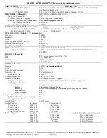
Страница 80: ...72 Chapter 9 Specifications ...

Страница 81: ...ng requirements are applicable to all countries and regions The length of the power cord set must be at least 1 5 m 5 0 ft and no more than 2 0 m 6 5 ft All power cord sets must be approved by an acceptable accredited agency responsible for evaluation in the country or region where the power cord set will be used The power cord sets must have a minimum current capacity of 10 A and a nominal voltag...

Страница 82: ...orea KTL 5 Sweden SEMKO 1 Switzerland SEV 1 Taiwan BSMI 6 Thailand TISI 1 The United Kingdom ASTA 1 The United States UL 2 1 The flexible cord must be Type HO5VV F 3 conductor 0 75mm2 conductor size Power cord set fittings appliance coupler and wall plug must bear the certification mark of the agency responsible for evaluation in the country or region where it will be used 2 The flexible cord must...

Страница 83: ...wall plug must bear the CCC certification mark 5 The flexible cord must be Type H05VV F 3X0 75mm2 conductor size KTL logo and individual approval number must be on each element Corset approval number and logo must be printed on a flag label 6 The flexible cord must be Type HVCTF 3X1 25mm2 conductor size Power cord set fittings appliance coupler cable and wall plug must bear the BSMI certification ...

Страница 84: ...76 Chapter 10 Power cord set requirements ...

Страница 85: ...he battery in general household waste Follow the local laws and regulations in your area for battery disposal HP encourages customers to recycle used electronic hardware HP original print cartridges and rechargeable batteries For more information about recycling programs see the HP Web site at http www hp com recycle 77 ...

Страница 86: ...78 Chapter 11 Recycling ...

Страница 87: ...cations 69 connector power 5 connectors service considerations 23 D display assembly illustrated 16 removing 43 display assembly subcomponents illustrated 19 removing 43 display bezel illustrated 19 removing 45 display cable illustrated 19 display enclosure illustrated 20 display panel illustrated 20 product description 1 removing 47 display specifications 70 drive light 5 E electrostatic discharg...

Страница 88: ...ription 3 USB 3 x SuperSpeed 6 USB Type C 3 x charging 5 power button identifying 10 power connector bracket illustrated 16 power connector cable illustrated 16 removing 57 power connector identifying 5 power cord requirements for all countries 73 requirements for specific countries and regions 74 set requirements 73 power light 5 power lights identifying 9 power requirements 4 processor product d...

Страница 89: ...g 53 spare part number 16 53 system recovery 63 system restore point creating 62 system restore point creating 61 T tools required 23 top cover keyboard removing 58 TouchPad buttons 8 TouchPad board removing 38 spare part number 16 38 TouchPad zone identifying 8 transfer board illustrated 20 removing 50 51 transfer board cable illustrated 20 transporting guidelines 25 traveling with the computer 1...

Страница 90: ...82 Index ...

Отзывы: