Open Energy for All
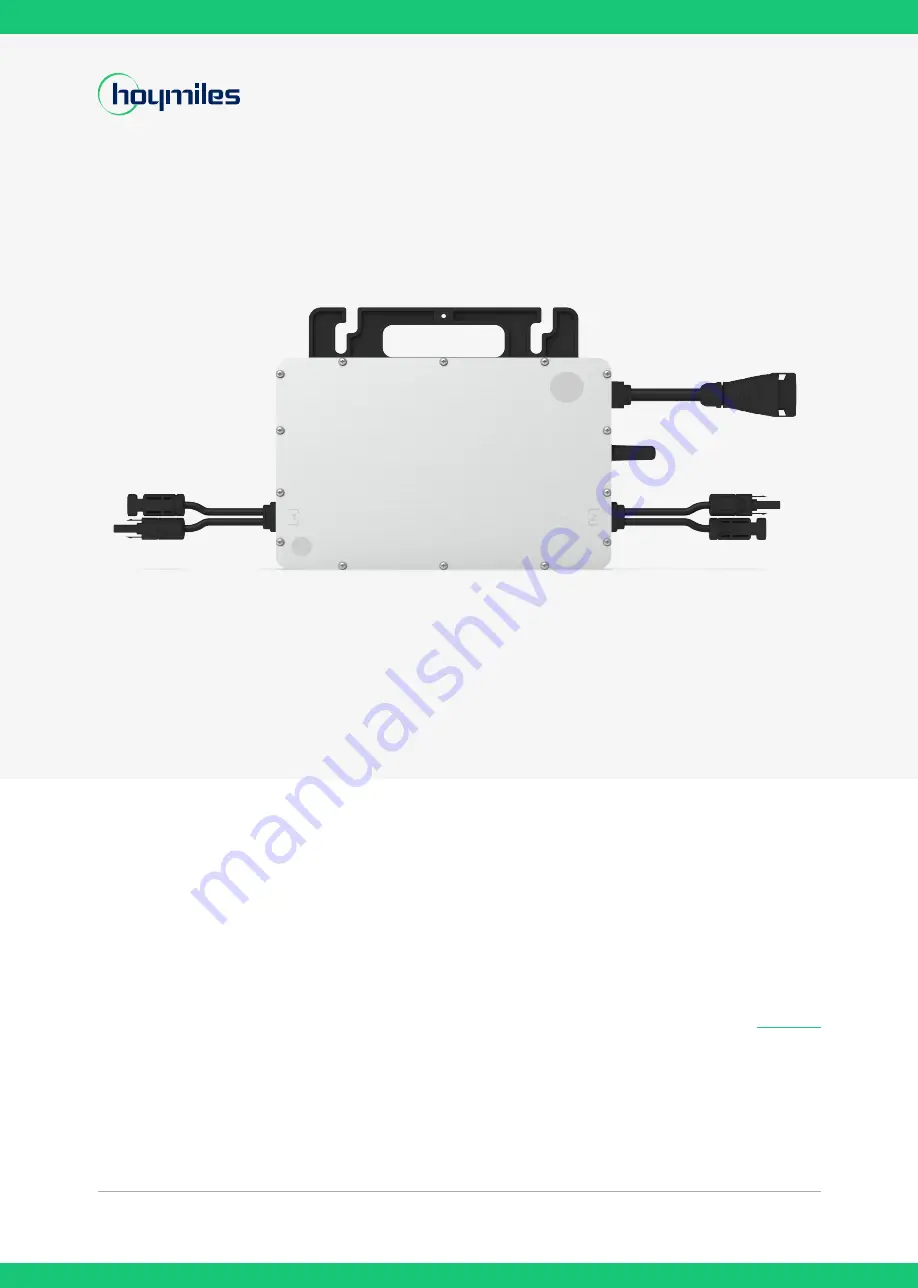
Single-phase Microinverter
HMS-700-2T-NA
HMS-800-2T-NA
HMS-900-2T-NA
HMS-1000-2T-NA
USER MANUAL
Region: North America V202201
hoymiles.com
Страница 1: ...Open Energy for All Single phase Microinverter HMS 700 2T NA HMS 800 2T NA HMS 900 2T NA HMS 1000 2T NA USER MANUAL Region North America V202201 hoymiles com...
Страница 2: ...ighly flexible and reliable as the system enables direct control of the production of each PV module About the Manual This manual contains important instructions for HMS 700 2T NA HMS 800 2T NA HMS 90...
Страница 3: ...4 1 Position and Space Required 10 4 2 Connecting Multiple PV Modules to Microinverter 10 4 3 Installation Tools 11 4 4 AC Branch Circuit Capacity 11 4 5 Precautions 12 5 Microinverter Installation 13...
Страница 4: ...tes a hazardous situation that can result in deadly electric shocks other serious physical injuries or fire incidents This indicates that directions must be strictly followed to avoid safety hazards i...
Страница 5: ...isconnect switches and Over Current Protection Devices OCPD Each input of the inverter is connected to one PV module Do not connect batteries or other sources of power supply The inverter can be used...
Страница 6: ...ger needed must be returned to an authorized dealer or approved collection and recycling facility Caution Do not come within 8 inches 20 cm of the microinverter when it is in operation Danger of high...
Страница 7: ...inverter is a module level solar inverter that tracks the maximum DC power point of each PV module which is known as Maximum Power Point Tracking MPPT This function of module level MPPT means that whe...
Страница 8: ...2 times longer distance than the 2 4GHz spectrum Interference Sub 1GHz wireless networking can handle interference better This is because it operates on a lower frequency so the communication between...
Страница 9: ...d 9 Single phase Microinverter HMS 700 800 900 1000 2T NA About Product Installation Preparation 3 7 Dimensions mm 3 6 Terminals Introduction Object Description A Sub 1G Wireless Terminal B DC Connect...
Страница 10: ...pace Required Please install the microinverter and all DC connections under the PV module to avoid direct sunlight rain exposure snow buildup UV etc The silver side of the microinverter should be up a...
Страница 11: ...4 208 V 5 240 V 4 208 V 4 240 V 3 208 V 4 240 V 20 A Maximum number per 10AWG branch 7 208 V 9 240 V 6 208 V 8 240 V 6 208V 7 240 V 5 208 V 6 240 V 30 A 4 4 AC Branch Circuit Capacity Hoymiles HMS 70...
Страница 12: ...ection Avoid direct sunlight to prevent power derating which can be caused by an increase in the internal temperature of the microinverter Keep the inverter in well ventilated place to avoid overheati...
Страница 13: ...H AC Trunk Connector Unlock Tool Note All accessories above are not included in the package and should be purchased separately About Installation 5 2 Installation Steps The order of Step 1 and Step 2...
Страница 14: ...sure ventilation and heat dissi pation 3 Mounting torque of the 8 mm screw is 9 N m Do not over torque 4 Do not pull or hold the AC cable with your hand Hold the handle instead Step 2 Plan and Build t...
Страница 15: ...the port Plug the upper cover back to the Trunk connector About Installation 2 Install the AC Trunk End Cap at one side of AC Trunk Cable the end of AC Trunk Cable 3 Install AC end cable on the other...
Страница 16: ...cable to the distribution box and wire it to the local grid network Product information is subject to change without notice Please download reference manuals at www hoymiles com click Step 4 Create an...
Страница 17: ...is required 2 If the alarm occurs frequently and cannot be recovered contact your dealer or Hoymiles technical support team 130 Offline 1 Please make sure that the microinverter works normally check i...
Страница 18: ...ncy may be just abnormal temporarily The microinverter can automatically recover after grid frequency becomes normal 2 If the alarm occurs frequently check whether the grid frequency change rate is wi...
Страница 19: ...check the DC cable connection between this port and the PV module 213 MPPT A PV 1 PV 2 abnormal wiring 1 Please check whether the DC connections on port 1 and 2 are correct 2 Check if the DC extension...
Страница 20: ...is abnormal Red flashes 0 5s gap Invalid AC grid or hardware failure Refer to Hoymiles Monitoring Platform for more details Red flashes 1s gap Not producing power due to invalid AC grid Solid red Har...
Страница 21: ...urself If the troubleshooting fails please return it to the factory for replacement 6 4 Routine Maintenance 1 Only authorized personnel are allowed to carry out the maintenance operations and are resp...
Страница 22: ...disconnect tool Remove the AC Sub Connector with AC disconnect tool Loosen the fixing screws on the top of the microinverter and remove the microinverter from the PV racking b How to replace the micro...
Страница 23: ...ays to avoid unforeseen injury Please examine the conditions of the components to be transported Upon receiving the microinverter you should check the container for any external damage and verify the...
Страница 24: ...r MPPT 1 Output Data AC Peak output power VA 700 800 900 1000 Maximum continuous output power VA 638 720 820 958 Maximum continuous output current A 2 66 3 07 3 3 46 3 42 3 94 3 99 4 61 Nominal output...
Страница 25: ...al electrical utility Simultaneous use of Fixed Power Factor and Volt Var is not supported Measurement Default Tolerance of Measurement Volts 1 Watts 5 VAr 6 Power factor 0 05 Hz 0 1 Hz Region Voltage...
Страница 26: ...ation N A N A Low Frequency 1 LF1 57 0 f 58 5 299 sec Mandatory Operation 300 sec 0 1 300 sec Low Frequency 2 LF2 f 57 0 No Ride Through Not Applicable 0 16 sec 0 16 sec Low Voltage 3 LV3 V 50 1 sec M...
Страница 27: ...HMS 900 2T NA HMS 1000 2T NA Output power rating W 638 720 820 958 Manufacturer s stated P f accuracy Prated 5 5 5 5 Maximum slope of frequency droop Prated Hz 100 100 100 100 Minimum slope of freque...
Страница 28: ...0 Appendix 1 10 1 Installation Map To sheet ______ To sheet ______ To sheet ______ To sheet ______ Sheet_____of_____ Hoymiles Microinverter Installation Map Please Make N for North 1 A B C D 2 3 4 5 6...
Страница 29: ...2022 Hoymiles Power Electronics Inc All rights reserved 29 Single phase Microinverter HMS 700 800 900 1000 2T NA 11 Appendix 2 11 1 WIRING DIAGRAM 120VAC 240VAC SPLIT PHASE...
Страница 30: ...2022 Hoymiles Power Electronics Inc All rights reserved 30 Single phase Microinverter HMS 700 800 900 1000 2T NA 11 Appendix 2 11 2 WIRING DIAGRAM 120VAC 208VAC THREE PHASE...