background image

2

GB

Installation

 Before operating your new appliance please read

this  instruction  booklet  carefully.  It  contains

important information concerning the safe operation,

installation and maintenance of the appliance.

 Please keep these operating instructions for future

reference. Pass them on to any new owners of the

appliance.

P

ositionin

g

 Keep all packaging material out of the reach of

children. It may present a choking or suffocation

hazard (

see Precautions and tips

).

 The appliance must be installed by a qualified

professional in accordance with the instructions

provided. Incorrect installation may cause harm to

people and animals or may damage property.

B

u

ilt-in


appliance

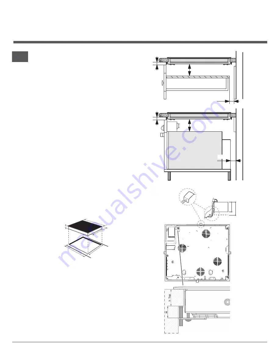
Use a suitable cabinet to ensure that the appliance

functions  properly.

• The supporting surface must be heat-resistant up

to a temperature of approximately 100°C.

• If the appliance is to be installed above an oven,

the oven must be equipped with a forced

ventilation  cooling  system.

• Avoid installing the hob above a dishwasher: if

this cannot be avoided, place a waterproof

separation device between the two appliances.

• Depending on the hob you want to install, the

cabinet must have the following dimensions (

see

figure

):

560 +

/- 1

490 +/- 1

48

590

520

V

entilation

To


allow


adequate


ventilation


and


to


avoid


overheating

of


the


surrounding


surfaces


the


hob


should


be


positioned

as


follows:

• At


a


minimum


distance


of

 4

0


mm


from


the


back

panel.

• So


that


a


minimum


distance


of

 2

0


mm


is

maintained


between


the


installation


cavity


and


the

cabinet


underneath.

• Kitchen


cabinets


ad

j

acent


to


the


appliance


and

taller


than


the


top


of


the


hob


must


be


at


least

 6

00

mm


from


the


edge


of


the


hob.

FRONT SIDE

OF HOB

SUPPORTING

SURFACE

30

40

UNDERSIDE

OF HOB

5 mm

min. 20 mm

min. 20 mm

min. 40 mm

COMPARTMENT

5 mm

min. 40 mm

FAN-ASSISTED

OVEN

Содержание CEM 645 D C

Страница 1: ... hob Precautions and tips 6 Practical advice on using the appliance General safety Disposal Care and maintenance 7 Switching the appliance off Cleaning the appliance Disassembling the hob Technical description of the models 8 After Sales Service 10 Guarantee 11 Key Contacts 12 CEM 645 D C CEM 645 D X CRM 641 D C CRM 641 D X HOB GB GB English 1 ...

Страница 2: ...tant up to a temperature of approximately 100 C If the appliance is to be installed above an oven the oven must be equipped with a forced ventilation cooling system Avoid installing the hob above a dishwasher if this cannot be avoided place a waterproof separation device between the two appliances Depending on the hob you want to install the cabinet must have the following dimensions see figure 56...

Страница 3: ...the lower part of the appliance there is a connection box for the different types of electricity supply the picture is only an indication and is not an exact representation of the purchased model Single phase connection The hob is equipped with a pre connected electricity supply cable which is designed for single phase connection Connect the wires in accordance with the instructions given in the f...

Страница 4: ...n has been made and that it is fully compliant with safety regulations Before connecting the appliance to the power supply make sure that The appliance is earthed and the plug is compliant with the law The socket can withstand the maximum power of the appliance which is indicated on the data plate located on the appliance itself The voltage falls within the range of values indicated on the data pl...

Страница 5: ...ear a slight click to enable the maximum power level This in turn can be adjusted to a value between 12 and 1 by turning the knob anticlockwise To restore the minimum power level turn the knob and set it back to position 0 For double cooking zones the first part of the knob movement activates the smaller internal cooking zone To activate both internal and external it is necessary to turn the knob ...

Страница 6: ...insimmediatelyandcontactaServiceCentre Ensurethatpowersupplycablesofotherelectricalappliances do not come into contact with the hot parts of the hob Rememberthatthecookingzonesremainrelativelyhotforat least thirty minutes after they have been switched off An indicatorlightprovidesawarningwhenresidualheatispresent seeStart upanduse Keep any object which could melt away from the hob for exampleplast...

Страница 7: ...mediately with the scraper while the surface is still hot Once it is clean the hob may be treated with a special protective maintenance product the invisible film left by this product protects the surface from drips during cooking This maintenance task should be carried out while the appliance is warm not hot or cold Always remember to rinse the appliance well with clean water and dry it thoroughl...

Страница 8: ...of each cooking zone Hobs CEM 645 D C CEM 645 D X CRM 641 D C CRM 641 D X Cooking zone Power W Diameter mm Power W Diameter mm Back Left A 2500 210 HD 2200 800 210 140 Back Right H 1400 160 H 1400 160 Front Left H 1200 145 H 1200 145 Front Right HD 1700 700 180 120 H 1800 180 Total power 6800 6600 Key H single hilight HD double hilight A single halogen ...

Страница 9: ...9 GB ...

Страница 10: ...fully trained engineers All repairs include a parts and labour guarantee for 12 months from the date of the repair If you require any information or have any questions about your appliance our operators are on hand with help and advice All this ensures that you will receive the best available after sales service possible Extended Warranties UK 08709 088 088 www theservicecentre co uk Republic of I...

Страница 11: ...ct to the following provisions that your appliance Has been installed and used correctly in accordance with this instruction booklet Has been used solely for domestic purposes and is located on domestic premises ie not for commercial or trade use Has been properly connected to a suitable electrical supply voltage as stated on the appliance rating plate Has not been subject to misuse accident modif...

Страница 12: ...heservicecentre co uk Republic of Ireland 1850 302 200 Note Our operators will require the following information Model number Serial number Extended Warranties UK 08709 088 088 Open 8 to 8 Mon Sun www theservicecentre co uk Republic of Ireland 1850 502 200 Genuine Parts and Accessories UK 08709 077 077 Open 8 30 to 5 30 Mon Fri 9 to 12 Sat www theservicecentre co uk Republic of Ireland 01 842 6836...

Отзывы: