background image

-12-

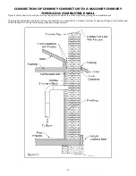
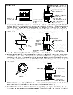
SHEET STEEL SUPPORTS

CHIMNEY SECTION

CHIMNEY

CONNECTOR

AIR SPACE

2 IN.

FIGURE 12, PART D

MINIMUM CLEARANCE

2 IN.  ALL AROUND

CHIMNEY THIMBLE

1 IN. AIR SPACE TO

CHIMNEY LENGTH

MASONRY CHIMNEY CONSTRUCTED

TO NFPA 211

SHEET STEEL SUPPORTS

(24 GAUGE MIN. THICKNESS)

CHIMNEY

 FLUE

MINIMUM CHIMNEY CLEARANCES FROM MASONRY TO

SHEET STEEL SUPPORTS AND COMBUSTIBLES 2 IN.

CHIMNEY CONNECTOR

TO HEATER

SOLID INSULATED, LISTED

FACTORY-BUILT CHIMNEY

 LENGTH (12 IN. LONG MIN.)

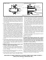
in the combustible wall shall be covered and the thimble 

supported with sheet steel supports which are at least 24 

gauge (0.024") in thickness.  The sheet steel supports shall 

be securely fastened to wall surfaces on all sides and shall 

be sized to fit and hold the chimney section.  Fasteners used 

to secure chimney sections shall not penetrate chimney flue 

liner.  See Part C.

4. Use an 8" inside diameter solid insulated listed factory-built 

chimney length which has 1" or more of solid insulation. The 

minimum length of this chimney section shall be 12" and 

will serve as a pass-through for the 6" diameter chimney 

connector.  There must be at least a 12" air space between 

the outer wall of the chimney section and any combustible 

materials.  The chimney section shall be concentric with 

and spaced 1" away from the chimney connector by means 

of sheet steel support plates on both ends of the chimney 

section.  The opening in the combustible wall  shall be cov

-

ered and the chimney section supported on both sides with 

sheet steel supports which are at least 24 gauge (0.024") 

in thickness.  The sheet steel supports shall be securely 

fastened to wall surfaces on all sides and shall be sized to 

fit and hold the chimney section.  Fasteners used to secure 

chimney sections shall not penetrate chimney flue liner. See 

Part D.

5. A listed factory-built wall pass-through system may be pur

-

chased and installed according to the instructions packaged 

with it to provide a safe method of passing the chimney 

connector through a combustible wall for connection to a 

masonry chimney.

Additional requirements pertaining to Figure 8 and 

the above wall pass-through systems:

1. Insulation material used as part of wall pass-through sys

-

tem shall be of noncombustible material and shall have a 

thermal conductivity of 1.0 Btu • in./ft.² • °F (4.88 kg • cal/

hr • m² • °C) or less.

2. All clearances and thicknesses are minimums:  larger clear

-

ances and thickness are acceptable.

3. A chimney thimble, as shown for 3" and 4" above (Parts C 

and D) shall be for types "3" and 4" connections to facili

-

tate removal of the chimney connector for cleaning. The 

chimney thimble shall be of ASTM C315 fireclay with 5/8" 

minimum wall thickness, or material or equivalent durabil

-

ity. The inside diameter of the thimble shall be sized for 

the  proper  snug  fit  of  a  6"  diameter  chimney  connector 

pipe. The thimble shall be installed without damage to the 

chimney flue. The thimble shall extend through the chimney 

wall to, but not beyond, the inner surface of the chimney 

flue and shall be permanently cemented in place with high 

temperature cement.

4. A chimney connector to a masonry chimney, except for 2" 

above (Part B), shall extend through the wall pass-through 

system to the inner face of the chimney flue, but not beyond. 

It does not have to be fastened in place so long as it cannot 

accidently be pulled out of the chimney or shoved into the 

chimney flue. If fasteners are used  to secure the chimney 

connector to a masonry chimney, the fasteners shall not 

penetrate the chimney flue liner.

5. Any material used to close up any opening for the connector 

shall be noncombustible.

PART E - (Figure 12)
In addition to the methods shown by A, B, C, and D of 

Figure 12, a listed factory-built wall pass-through system 

may be purchased and installed according to the instruc-

tions packaged with it to provide a safe method of pass-

ing chimney connector through a combustible wall for a 

connection to a masonry chimney.

If the chimney connector does not have to pass through a 

combustible wall to get to a masonry chimney, simply con

-

nect the chimney connector directly to the masonry chimney's 

chimney thimble as described and shown by parts C and D of 

Figure  12.  Remember, the chimney connector should extend 

into the chimney thimble to the inner face of the chimney flue 

but not beyond;  if the chimney connector is extended through 

the chimney thimble into the chimney flue, resistance to the 

flow of smoke and gases up the chimney will occur;  that flow 

resistance will have an adverse affect on the operation and 

performance of the heater and venting system.

CONNECTION OF CHIMNEY CONNECTOR TO A MASONRY CHIMNEY WHEN CHIMNEY CONNECTOR

DOES NOT PASS THROUGH A COMBUSTIBLE WALL

Содержание 1300

Страница 1: ...CE THE 1500 HOTBLAST FURNACE HAS BEEN APPROVED FOR U S INSTALLATIONS ONLY ALL MODELS CERTIFIED UNDER UL 391 THE 1300 MODEL IS ALSO CERTIFIED UNDER CAN CSA B366 1 M91 851486N 1901G CAUTION READALLINSTRUCTIONSCARE FULLY BEFORE STARTING THE INSTALLATIONOROPERATING THE FURNACE IMPROPER INSTALLATION MAY VOID YOUR WARRANTY DO NOT USE THIS FURNACE IN A MOBILE HOME OR TRAILER U S Environmental Protection ...

Страница 2: ...t Safety Glasses MATERIAL 6 Pipe 6 Elbow Collar and Thimble as required 24 gauge min 1 2 Sheet Metal Screws 6 Inside diameter Listed Residential Type or Building Heating Appliance Chimney or existing masonry chimney Electrical Wiring 6 Draft Regulator 1 2 Conduit Conduit Connectors Furnace Cement Manufacturer Recommends Rutland Black Code 78 or Equivalent Plenum and Duct work as required TOOLS AND...

Страница 3: ...AFETY NOTICE If this heater is not properly installed a house fire may result For your safety follow the installation directions Contact local building or fire of ficials about restrictions and installation inspection requirements in your area If not already installed we recommend that smoke detectors be installed CAUTION CLEANOUT OF THE HEAT EXCHANGER FLUE PIPE CHIMNEY AND DRAFTINDUCER IFUSED ISE...

Страница 4: ...PA 211 The address of the NFPA is Batterymarch Park Quincy MA 02269 11 Keep the ashpit section free of excess ashes Do not al low ashes to stack higher than the sides of the ash pan 12 DISPOSAL OFASHES Place ashes in a metal container with a tight fitting lid Keep the closed container on a noncombustible floor or on the ground well away from all combustible materials Keep the ashes in the closed c...

Страница 5: ...TRAL FURNACE INSTALLATION As a central furnace the unit functions independently of any other system The blower will come on when the plenum temperature reaches the setting on the blower control PARALLEL INSTALLATION U S ONLY The design is such that when the blower comes on the blower on the central system also comes on The blower will only come on when the temperature in the plenum has reached the...

Страница 6: ... 6 DIMENSIONS OF FURNACE Figure 2 Model 1500 Figure 1 Model 1300 ...

Страница 7: ...tible surfaces If you have a solid brick or stone wall behind your furnace you can place the furnace as close as you wish to the wall If the wall is only faced with brick or stone treat it as a combustible wall 18 18 6 SOLID DAMPER 6 BAROMETRIC DRAFT REGULATOR NON COMBUSTIBLE FLOOR 12 9 48 18 CENTRAL FURNACE 6 CHIMNEY 21 Figure 4 Figure 5 1300 1500 Unit to Sidewall 12 305mm 12 305mm Unit to Backwa...

Страница 8: ...manufacturer s instructions Use only a Listed Residential Type or Building Heating Appliance Chimney If your chimney starts at the ceiling Fig 7 you will need enough 6 pipe to reach the ceiling The top of the chimney must be at least 3 feet above the roof and be at least 2 feet higher than any point of the roof within 10 feet Fig 7 IMPORTANCE OF PROPER DRAFT Draft is the force which moves air from...

Страница 9: ... same room same pressure zone as the furnace 8 Install the barometric draft regulator strictly in accordance with the instructions that are provided with the barometric draft regulator 9 A solid damper must be used in the chimney connecting pipes be tween the flue collar and the chimney When used in conjunction with a barometric draft regulator the solid damper must be placed between the barometri...

Страница 10: ...ow to connect the chimney connector of a heater to a masonry chimney through a combustible wall There are five allowable ways that a chimney connector can be connected to a masonry chimney by passing through a combustible wall NFPA Standard 211 allows the following wall pass through systems Figure 11 ...

Страница 11: ...ATTACH CONNECTOR SECURELY AIR SPACE inner surface of the chimney flue and shall be firmly cemented in place See Part A 2 Use a solid insulated listed factory built chimney length having an inside diameter of 6 and having 1 or more of solid insulation There must be at least a 9 air space between the outer wall of the chimney length and any combustible materials The inner end of the chimney length s...

Страница 12: ... thermal conductivity of 1 0 Btu in ft F 4 88 kg cal hr m C or less 2 All clearances and thicknesses are minimums larger clear ances and thickness are acceptable 3 A chimney thimble as shown for 3 and 4 above Parts C and D shall be for types 3 and 4 connections to facili tate removal of the chimney connector for cleaning The chimney thimble shall be of ASTM C315 fireclay with 5 8 minimum wall thic...

Страница 13: ...with screws and nuts provided Note Slotted holes are for adjustment of handle Adjust handle until some pressure is required to lock feed door during firing sequence 5 Install the thermodisc on rear of furnace cabinet with the two screws provided Mount the conduit assembly from the junction box to the thermostat bracket Crimp the two female terminals to each of the wire leads Plug the wires to the ...

Страница 14: ... wiring wires M1 M2 of one blower motor Wire leads from the distribution blower are usually BOTH BLACK Makes no difference which leads from the motor s connects to the cor responding leads coming out of the conduit Figure 16 WIRING DIAGRAM ...

Страница 15: ...ement The chimney connector shall be securely supported and joints fastened with sheet metal screws or rivets e Install 8 diameter heat pipe to plenum of the central hot air furnace Use 26 gauge pipe and connectors to be purchased separately If central air conditioning is installed in the plenum install heat pipe above the air conditioning unit Secure heat pipe connection with supports and sheet m...

Страница 16: ... the new gasket You may light up your stove again approximately24hoursafterhavingcompletedthisoperation This unit s ash door uses a 5 8 diameter rope gasket This unit s feed door uses a 1 2 diameter rope gasket SERVICE HINTS Do not expect a furnace to draw It is the chimney that creates the draft Smoke spillage into the house or excessive build up of water or creosote in the chimney arewarningstha...

Страница 17: ...uel B Check length of flue pipe to chimney Your unit should be within six 6 feet of your chimney C Make sure chimney cap is not too close to the top of the chimney D Check chimney draft make sure chimney flue pipe is clean and chimney is of adequate height E Slide baffle should be pulled out prior to load door opening 4 Problem Distribution blower vibrating Solution A Tighten blower wheel to motor...

Страница 18: ... 36 34 39 38 37 41 34 35 39 37 38 40 40 42 34 22 6 8 7 9 20 18 19 17 16 14 10 15 11 12 13 21 1 5 2 3 4 1 28 27 26 29 30 31 24 25 32 33 23 36 34 39 38 37 41 34 35 39 3 3 40 42 34 22 6 8 7 9 20 18 16 14 10 15 11 12 13 21 1 5 2 3 4 1 28 27 26 29 30 31 24 25 32 33 23 38 37 41 34 35 39 37 38 40 40 42 34 1300 1500 ...

Страница 19: ...Collar Ring 1 24 22762B Forced Draft Ring 1 25 86402 1 1 2 Pipe Plug 1 26 80230 Blower 1300 1 1500 2 27 89319 Gasket Blower 1300 1 1500 2 28 83340 1 4 20 Clipnut 1300 4 1500 8 29 22140 Relay Box Bracket 1 30 80131 Junction Box 4 x 4 1 31 80231 Junction Box Cover 1 32 80314 Thermodisc 60T12 1 33 68234 Blower Thermostat Bracket 1 34 89066 Firebrick 4 5 x 9 x 1 25 1300 10 1500 12 36 40264 Liner Front...

Страница 20: ...83172 10 Sheet Metal Screw 6 8 89041 Spring 1 9 89175 Thermostat Knob 1 10 23425 Handle Bracket 2 11 89520 Wooden Handle 1 12 86318 Thermostat Chain 542 FT 13 68217 Feed DoorAssembly Includes Door and Gasket 1 N S 83106S Machine Screw 10 24 x 1 2 SL HD Z 2 N S 83136 Washer 9 32 I D 5 8 O D 1 16 THK 1 N S 83816 Cotter Pin 1 16 x 3 4 1 Parts Diagram List IN ORDER TO MAINTAIN WARRANTY COMPONENTS MUST...

Страница 21: ...uses a standard 16 x 20 x 1 filter NOT INCLUDED to reduce the amount of dust particles from being transferred thru you duct work system DR 6 Barometric Damper Regulator In the unlikely event that your furnace overfires a condition evidenced by elbows stove pipes and connectors glowing red in appearance or otherwise discoloring then your in stallation is subject to excessive draft created by either...

Страница 22: ...irebox The first flames will be long and generally orange or yellow and produce quite a bit of smoke As the gases burn off the flames become shorter change color and produce less smoke Once the fire is WELL ESTABLISHED add coal to the center of the firebox forming the cone Burning in this fashion allows heat to drive off the volatile gases and turbulence created increases the burn efficiency There...

Страница 23: ...utes until the volatile gases have burned off It is not necessary to shake down the ashes each time you refuel the furnace Experience will be your best teacher BANKING THE FIRE For extended operation such as overnight the fire will need to be banked To do so heap coal up along the sides and back of the firebox so that the fire gradually burns it over a longer period of time The intensity of the fi...

Страница 24: ... 24 CENTRAL INSTALLATION ADD ON INSTALLATION ...

Страница 25: ...DAIR RETURN TOEXISTING DUCTWORK WARMAIR EXISTING FURNACE SOLIDFUEL FURNACE FILTERBOX PLENUM COLLECTOR BOX COLDAIR RETURN TOEXISTING DUCTWORK WARMAIR EXISTING FURNACE SOLIDFUEL FURNACE FILTERBOX COLDAIR RETURN PLENUMTOP OPTIONAL Appendix INSTALLATION A INSTALLATION B INSTALLATION C ...

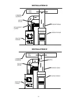
Страница 26: ... 26 INSTALLATION D INSTALLATION E ...

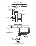
Страница 27: ... 27 INSTALLATION F INSTALLATION G ...

Страница 28: ... 28 INSTALLATION H TOP VIEW FRONT VIEW ...

Страница 29: ... as a result of their breach of this written warranty or any implied warranty 2 Should the heater be replaced by United States Stove Company free of charge all further warranty obligations are thereby met 3 Parts and or service replacements made under the terms of this warranty are warranted only for the remaining period of the original heater warranty 4 Without specific written exclusionary waiver...

Страница 30: ...ompany ________________________________________ Telephone No ______________________________________ Stove Inspected Chimney Swept Items Replaced ____________________________________ Service 05 Date ________________________ Engineer Name _____________________________________ Company __________________________________________ Telephone No ______________________________________ Stove Inspected Chimne...

Страница 31: ... 31 NOTES ...

Страница 32: ...ÛR POUR RÉFÉRENCE FUTURE LORS DE L ÉCRITURE TOUJOURS DONNER LE NUMÉRO DE MODÈLE COMPLET QUI SE TROUVE SUR LA PLAQUE SIGNALÉTIQUE FIXÉE SUR L APPAREIL DE CHAUFFAGE LORS DE LA COMMANDE DES PIÈCES DE RECHANGE FOURNIR LES INFORMA TIONS SUIVANTES COMME INDIQUÉ DANS CETTE LISTE 1 THE PART NUMBER LE NUMÉRO DE PIÈCE__________________________________ 2 THE PART DESCRIPTION LA DESCRIPTION DE LA PIÈCE_______...

Страница 33: ..._________________ Company__________________________________________ N de téléphone ___________________________________ Poêle Inspecté Cheminée Swept Articles Remplacé __________________________________ Date________________________ Ingénieur Nom _____________________________________ Service de 06 Refustratuib No ____________________________________ Company__________________________________________ ...

Страница 34: ... indirects spéciaux ou dommages éventuels que quiconque pour rait subir à la suite d une violation de cette garantie écrite ou de toute garantie implicite 2 Si l appareil de chauffage est remplacé gratuitement par United States Stove Company toutes les autres obligations de garantie sont ainsi satis faites 3 Le remplacement des pièces et ou le service effectués en vertu des modalités de cette gara...

Страница 35: ...d four à combustible solide four à combustible solide four plénum four existant travail de canard travail de canard INSTALLATION F INSTALLATION G dégagement minimal 2po dégagement minimal 2po retour d air froid à l installation centrale du four retour d air froid four à combustible solide four à combustible solide four plénum four existant travail de canard travail de canard dégagement minimal 2po...

Страница 36: ... d air froid plénum supérieur en option retour d air froid air chaud air chaud Pour les conduits existants pour les conduits existants air chaud Pour les conduits existants four existant four existant four existant four à combustible solide four à combustible solide four à combustible solide Plenum ...

Страница 37: ...ER SUR L INSTALLATION conduit d air froid conduit d air froid tuyau 8po tuyau 6po tuyau 6po Coude à 90 Coude à 90 Amortisseur Amortisseur Connecteur de tuyau Connecteur de tuyau Gaz existant huile four électrique Four Four optionnel ...

Страница 38: ...nutes jusqu à ce que les gaz volatils ont brûlé Il est pas nécessaire de secouer les cendres chaque fois que vous ravitailler en carburant du four L expérience sera votre meilleur professeur Banque du feu Pour une utilisation prolongée par exemple la nuit le feu devra être mis en banque Pour ce faire du charbon de façon tas le long des côtés et l arrière de la chambre de combustion afi n que le fe...

Страница 39: ...e la chambre de combustion Les premières fl ammes seront longues et généralement orange ou jaune et produire un peu de fumée Comme les gaz brûlent les fl ammes deviennent plus courtes le changement de couleur et produisent moins de fumée Une fois que le feu est bien établi ajouter du charbon au centre de la chambre de combustion formant le cône Brûler de cette façon permet à la chaleur pour chasse...

Страница 40: ...20 x 1 fi ltre standard non inclus pour réduire la quantité de particules de poussière d être transféré à travers votre système de travail conduit DR 6 Barométrique Damper Régulateur Dans le cas improbable où votre four overfi res une condition en évidence par les coudes les tuyaux de poêle et les connecteurs rougeoyant en apparence ou autrement décolorer puis votre installation est soumise à un t...

Страница 41: ...ment couleur vert 1 3 23429 Étape Plate Thermostat 1 4 23431 friction Plate 1 5 81903 Thermostat 1 6 23427 Thermostat support de montage 1 7 83172 10 Sheet Metal Screw 6 8 89041 Printemps 1 9 89175 thermostat Knob 1 10 23425 Poignée Support 2 11 89520 Manche en bois 1 12 86318 Chain thermostat 542 FT 13 68217 Nourrissez Porte Comprend porte et joint 1 N S 83106S Screw Machine 10 24 x 1 2 SL HD Z 2...

Страница 42: ... 1300 1 68228 1500 22 23397 Baffl e Flue 1300 1300 1 23398 1500 2 23 22761B Ring Collar Flue 1 Clé Numéro de la partie Description Modèle Qté 24 22762B Forcé Projet Anneau 1 25 86402 1 1 2 Plug pipe 1 26 80230 Ventilateur 1300 1 1500 2 27 89319 Joint Blower 1300 1 1500 2 28 83340 1 4 20 Clipnut 1300 4 1500 8 29 22140 Boîte Relais Bracket 1 30 80131 Junction Box 4 x 4 1 31 80231 Junction Box Cover ...

Страница 43: ...8 37 41 34 35 39 37 38 40 40 42 34 Pièces de rechange 1300 1500 22 6 8 7 9 20 18 19 17 16 14 10 15 11 12 13 21 1 5 2 3 4 1 28 27 26 2 3 24 25 32 33 23 36 34 39 38 37 41 34 35 39 40 42 34 22 6 8 7 9 20 18 16 14 10 15 11 12 13 21 1 5 2 3 4 1 28 27 26 29 30 31 24 25 32 33 23 38 37 41 34 35 39 37 38 40 40 42 34 ...

Страница 44: ...fi ez la longueur du conduit de fumée à la cheminée Votre appareil doit être dans les six 6 pieds de votre cheminée C Assurez vous que le chapeau de cheminée ne soit pas trop proche du haut de la cheminée D Vérifi er tirage de la cheminée assurez vous conduit d une cheminée est propre et de la cheminée est de taille adéquate E Glisser chicane doit être retirée avant de charger l ouverture de la po...

Страница 45: ...e chaude ce qui empêche cette condensation 5 Si le feu brûle bien mais parfois fume ou brûle lentement il peut être causé par le haut de la cheminée étant inférieure à une autre partie de la maison ou un arbre voisin Le vent qui souffl e sur une maison ou un arbre tombe sur le dessus de la cheminée comme de l eau sur un barrage en battant en bas de la fumée Le sommet de la cheminée doit être d au ...

Страница 46: ...r des dommages permanents Enlèvement et disposition des cendres Lorsque les cendres atteignent 8 à 10 cm 3 à 4 po d épaisseur dans votre boîte à feu ou bac à cendres et que le feu est éteint et froid retirez les cendres en excès Laissez un lit de cendres d environ 3 cm 1 po d épaisseur sur le fond de la boîte à feu pour aider à conserver une couche chaude de charbon Les cendres doivent être placée...

Страница 47: ... mm Dos 18 po 460 mm La fournaise ne peut être installée que sur un sol de matériaux non infl ammables d Installer un raccord de conduit de fumée à la cheminée en utilisant des tuyaux et coudes de calibre 26 doivent être achetés séparément en vous assurant de conserver les espaces de dégagement appropriés pour le modèle en question Sceller le conduit de fumée à l aide de mastic à fournaise Le racc...

Страница 48: ...eurs correspondants sortant du conduit Vert Sol Source de courant Fil code couleur Contrôle du ventilateur Moteur de la soufflante Moteur de la soufflante Contrôle du ventilateur Source de courant V V Thermodisque Sol N N N Moteur de la soufflante Important câblage d alimentation ne doit pas être inférieure à 90 centigrades Moteur de la soufflante N N B Boîte de jonction électrique N B R1 R2 M1 M2...

Страница 49: ...verrouillage au panneau de chargement comme illustré à la fi gure 10 à l aide des vis et des écrous fournis À noter les fentes servent à l ajustement de la poignée Procéder à l ajustement jusqu à ce qu une certaine pression soit nécessaire pour verrouiller le panneau de chargement au cours des allumages 5 Installer la commande du ventilateur et du régulateur Honeywell à l arrière du caisson de la ...

Страница 50: ...m plus grand que le conduit de raccordement de la cheminée de 6 po 152 4 mm Utiliser cette section en tant que passage pour un conduit de raccordement en acier à paroi simple de calibre 24 au minimum Garder la section Solid Pak concentrique et espacée de 25 4 mm 1 po du conduit de raccordement de la cheminée à l aide de plaques de soutien en tôle aux deux extrémités de la section de la cheminée Re...

Страница 51: ...ord de cheminée à la cheminée de maçonnerie en passant à travers un mur de matériaux inflammables La fi gure 8 illustre la façon de raccorder le raccord de cheminée d un appareil de chauffage à une cheminée de maçonnerie en passant à travers un mur fait de matériaux infl ammables Cinq façons de raccorder un raccord de cheminée à une cheminée de maçonnerie en passant à travers un mur de matériaux i...

Страница 52: ...lateur barométrique de tirage doit être installé dans la même pièce que la fournaise même zone de pression 8 Installer le régulateur barométrique de tirage en respectant scrupuleusement les instructions fournies avec celui ci 9 Un registre solide doit être utilisé dans les tuyaux de raccordement de la cheminée entre la buse et la cheminée Lorsqu il est utilisé de concert avec un régulateur baromét...

Страница 53: ...il de chauffage de bâtiment Si votre cheminée part du plafond voir fi gure 5 vous aurez alors besoin d une longueur de tuyau de 6 po suffi sante pour atteindre le plafond Le haut de la cheminée doit se trouver à au moins 3 pieds au dessus du niveau du toit et avoir au moins 2 pieds de plus que le point le plus élevé du toit dans un rayon de 10 pieds fi gure 5 Importance d un tirage adéquat Le tira...

Страница 54: ...s 4 Voir les fi gures 2 et 3 Vous assurer que vous respectez bien les espaces de dégagement montrés entre la fournaise et le tuyau de raccordement et les surfaces infl ammables Si le mur derrière votre fournaise est entièrement constitué de pierres ou de briques vous pouvez placer l appareil aussi près que le désirer de ce mur Si le mur a seulement une façade de pierres ou de briques il faut alors...

Страница 55: ... 6 DIMENSIONS DE LA FOURNAISE Figure 2 Models 1500 Figure 1 Model 1300 ...

Страница 56: ... une cheminée adéquate pour une utilisation avec les appareils de chauffage à combustible solide du type résidentiel ou de bâtiment La fournaise est conçue pour fonctionner dans un agencement en parallèle ou en série à évacuation d air avec un système de chauffage central ou comme appareil de chauffage central Installation en système de chauffage central Comme appareil de chauffage central l unité...

Страница 57: ...aise vous pouvez demander une copie de la publication Chimney s Fireplaces and Solid Fuel Burning Appliances de la NFPA National Fire Protection Association NFPA 211 L adresse de l association est Batterymarch Park Quincy MA 02269 Pour de plus amples informations sur l installation au Canada vous pouvez demander une copie du document CAN CSA B365 M91 Code d installation pour les appareils et l équ...

Страница 58: ...toucher lorsque la fournaise fonctionne RECOMMANDATION DE SÉCURITÉ Une mauvaise installation de cet appareil de chauffage peut provoqué un incendie de la résidence Pour votre sécurité veuillez suivre les directives d installation Contacter le personnel du bureau local du bâtiment ou du département des incendies pour connaître les restrictions et les exigences relatives à l installation en vigueur ...

Страница 59: ...ine pour tuyau tel que recommandé calibre 24 min Vis à tôle de po Cheminée répertoriée de type résidentiel ou pour appareil de chauffage avec un diamètre intérieur de 6 po ou cheminée existante en maçonnerie Câblage électrique Régulateur de tirage de 6 po Conduit de po raccords de conduit Mastic à fournaise recommandation du fabricant Rutland Black Code 78 ou l équivalent Chambre à air et canalisa...

Страница 60: ... FOURNAISE 1500 HOTBLAST a été approuvé pour INSTALLATIONS US SEULEMENT TOUS LES MODÈLES CERTIFIÉS SOUS UL 391 MODÈLE 1300 sont également certifiés CAN CSA B366 1 M91 PRUDENCE LIRE TOUTES LES INSTRUCTIONS A V A N T D E C O M M E N C E R L INSTALLATION OU D UTILISER LA FOURNAISE MAUVAISE INSTALLATION PEUT ANNULER LA GARANTIE NE PAS UTILISER CETTE CHAUDIÈRE DANS UNE MAISON MOBILE OU TRAILER Agence d...

Отзывы: