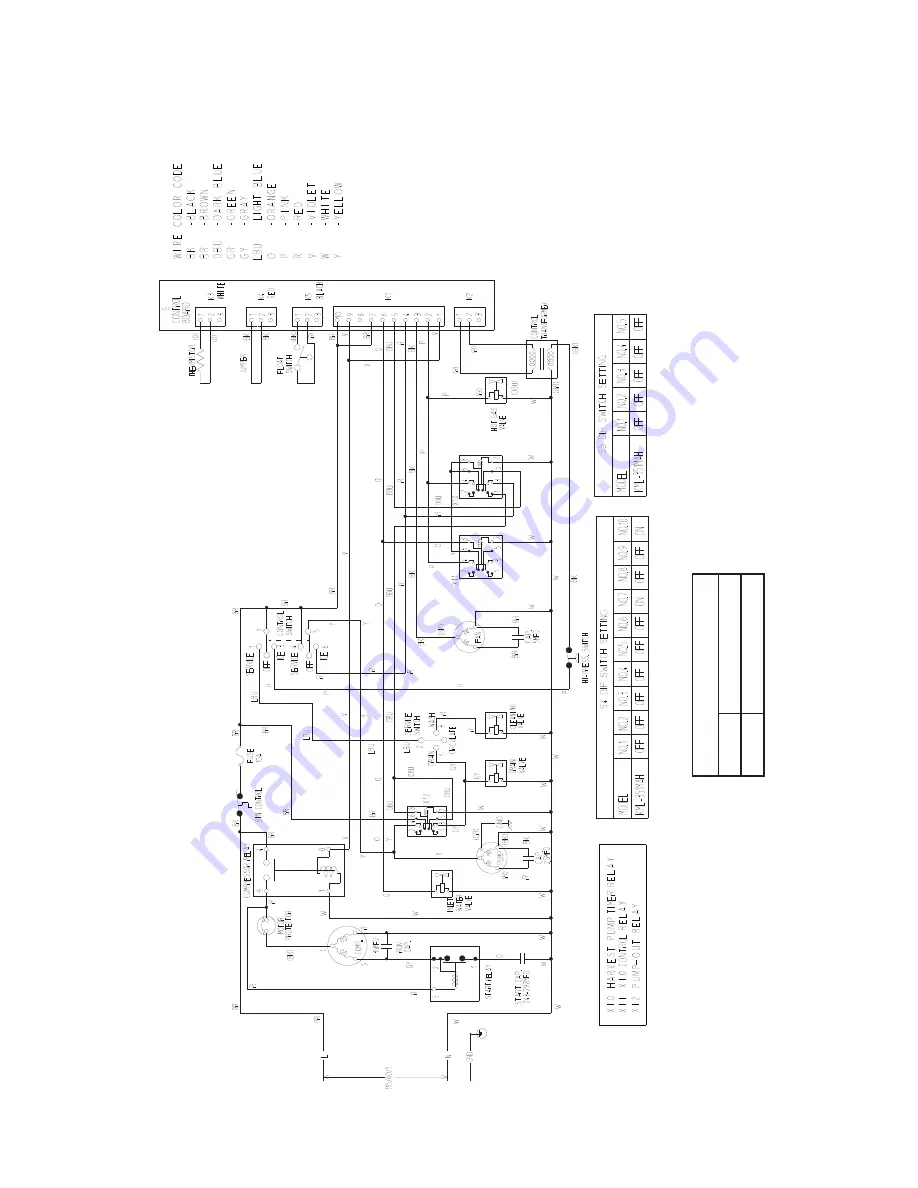
B. Wiring Diagram
1. KML-351MAH V-1 and Later
*High-P
ressur
e S
witc
h
Cut-out
41
2±
22
PSIG
Cut-in
327±22 PSIG
A-2
*
0
Страница 1: ...Hoshizaki A Superior Degree of Reliability www hoshizaki com Models KML 351MAH KML 351MWH Low Profile Modular Crescent Cuber Hoshizaki America Inc SERVICE MANUAL Number 73149 Issued 6 10 2008...
Страница 2: ...Should the reader have any questions or concerns which have not been satisfactorily addressed please call write or send an e mail message to the Hoshizaki Technical Support Department for assistance...
Страница 3: ...rature Safety 17 d Low Water Safety 17 e High Voltage and Low Voltage Cut outs 17 f LED Lights and Audible Alarm Safeties 18 3 Controls and Adjustments 19 a Default Dip Switch Settings 19 b Harvest Ti...
Страница 4: ...is Frozen Up 36 3 Low Ice Production 38 4 Abnormal Ice 39 5 Other 40 V Removal and Replacement of Components 41 A Service for Refrigerant Lines 41 1 Refrigerant Recovery 41 2 Brazing 41 3 Evacuation...
Страница 5: ...and Maintenance Instructions 52 A Cleaning and Sanitizing Procedures 52 1 Cleaning Procedure 52 2 Sanitizing Procedure Following Cleaning Procedure 53 B Maintenance 54 C Preparing the Icemaker for Lo...
Страница 6: ...el Galvanized Steel Rear WEIGHT Net 154 lbs 70 kg Shipping 185 lbs 84 kg CONNECTIONS ELECTRIC Permanent Connection WATER SUPPLY Inlet 1 2 FPT DRAIN Outlet 3 4 FPT CUBE CONTROL SYSTEM Float Switch HARV...
Страница 7: ...zed Steel Rear WEIGHT Net 154 lbs 70 kg Shipping 185 lbs 84 kg CONNECTIONS ELECTRIC Permanent Connection WATER SUPPLY Inlet 1 2 FPT DRAIN Outlet 3 4 FPT CUBE CONTROL SYSTEM Float Switch HARVESTING CON...
Страница 8: ...IGHT Net 154 lbs 70 kg Shipping 185 lbs 84 kg CONNECTIONS ELECTRIC Permanent Connection WATER SUPPLY Inlet 1 2 FPT Condenser Inlet 1 2 FPT DRAIN Outlet 3 4 FPT Condenser Outlet 3 8 FPT CUBE CONTROL SY...
Страница 9: ...iary code S 0 Spray Tubes Water Supply Inlet Junction Box Condenser Condenser Fan Motor Control Box Drier Hot Gas Valve Compressor Float Switch Water Pump Bin Control Thermostat Control Switches Expan...
Страница 10: ...and later Spray Tubes Water Supply Inlet Junction Box Condenser Condenser Fan Motor Control Box Drier Hot Gas Valve Compressor Float Switch Water Pump Bin Control Thermostat Control Switches Expansion...
Страница 11: ...unction Box Condenser Control Box Drier Hot Gas Valve Compressor Float Switch Water Pump Control Switches Expansion Valve Spray Tubes Drain Valve Wash Valve Inlet Water Valve Liquid Line Valve Bin Con...
Страница 12: ...ergized during harvest for a maximum of 6 minutes or the length of harvest whichever is shorter At the end of harvest the control board checks the position of F S and proceeds to the freeze cycle if i...
Страница 13: ...her details see II C 3 b Harvest Timer dip switch 1 2 When the harvest timer completes its countdown the harvest cycle is complete and the freeze cycle starts The minimum total time allowed by the con...
Страница 14: ...r in control F S in control Initial startup always begins here E control board will have 5 second delay If F S is open compressor stops and cycle returns to 1 minute fill Legend Comp compressor DV dra...
Страница 15: ...discharge It is especially important to touch the metal part of the unit before handling or replacing the control board 3 Do not touch the electronic devices on the control board or the back of the co...
Страница 16: ...ply 8 Open Switch for C board and ALPINE board service boards only ALARM RESET Switch Freeze Timer LED Dip Switch Harvest Backup Timer LED Alarm Buzzer Power LED lights when power is supplied to the b...
Страница 17: ...wer on to reset the safety d Low Water Safety The control board checks the position of the float switch at the end of the initial one minute water fill cycle and at the end of each harvest cycle If th...
Страница 18: ...sec Type of Alarm Notes 1 High Evaporator Temp temperature 127 F 53 C Check for harvest problem stuck HGV or relay hot water entering unit stuck HM or shorted thermistor 2 Harvest Backup Timer harves...
Страница 19: ...9 10 Pump Out Frequency Control 5 6 Pump Out Timer 3 4 Harvest Timer 1 2 Normally off 7 8 b Harvest Timer dip switch 1 2 The harvest timer starts counting when the thermistor reads 48 F 9 C at the eva...
Страница 20: ...mer at pump out Pump out always occurs on the 2nd harvest after startup Then depending on the pump out frequency control setting dip switch 5 6 pump out occurs every cycle or every 2nd 5th or 10th cyc...
Страница 21: ...e control transformer secondary circuit Transformer output is 10 5V at 115V primary input If the secondary circuit has proper voltage and the red LED is off the control board is bad and should be repl...
Страница 22: ...ohibited range the icemaker operates continuously even if the ice storage bin is filled with ice Setting in the prohibited range might cause severe damage to the icemaker resulting in failure No adjus...
Страница 23: ...ition power is supplied to the pump only This operation can be used to circulate cleaner for extended periods of time over the outside surface of the evaporator c WASH The KML series utilizes a soleno...
Страница 24: ...Supply Wash Valve Spray Tubes Condenser High Pressure Switch Strainer Hot Gas Valve Discharge Line Access Valve Suction Line Expansion Valve Refrigeration Circuit Water Circuit Water Tank Evaporator...
Страница 25: ...rainer Hot Gas Valve Discharge Line Access Valve Suction Line Expansion Valve Refrigeration Circuit Water Circuit Drain Water Tank Evaporator Drier Thermistor Insulation Tube Float Switch Pump Motor D...
Страница 26: ...cooled auxiliary code S 0 and KML 351MWH water cooled all auxiliary codes High Pressure Switch Air Cooled Model Water Cooled Model Cut out 412 21 3 PSIG 384 21 3 PSIG Cut in 327 21 3 PSIG 284 21 3 PSI...
Страница 27: ...ssure Switch Air Cooled Model Water Cooled Model Cut out 412 21 3 PSIG 384 21 3 PSIG Cut in 327 21 3 PSIG 284 21 3 PSIG 0 0 1b KML 351MAH air cooled auxiliary codes T 0 and later Transformer Output 10...
Страница 28: ...3 53 0 20 70 21 80 27 90 32 min 100 38 70 21 80 27 90 32 min 100 38 70 21 228 8 16 1 253 17 8 281 19 8 80 27 247 17 4 285 20 0 311 21 8 90 32 253 17 8 312 21 9 339 23 8 PSIG kg cm 2 G 100 38 257 18 1...
Страница 29: ...0 29 65 0 25 70 21 80 27 90 32 min 100 38 70 21 80 27 90 32 min 100 38 70 21 240 16 9 261 18 3 285 20 0 80 27 256 18 0 288 20 2 310 21 8 90 32 261 18 3 310 21 8 333 23 4 PSIG kg cm2 G 100 38 284 20 0...
Страница 30: ...9 270 19 0 279 19 6 90 32 269 18 9 270 19 0 278 19 5 PSIG kg cm 2 G 100 38 272 19 1 272 19 1 285 20 0 70 21 54 3 8 54 3 8 55 3 9 80 27 54 3 8 54 3 8 55 3 9 90 32 54 3 8 55 3 8 55 3 9 PSIG kg cm2 G 10...
Страница 31: ...ntil water enters and the float switch closes low water safety protection during initial start up and at the end of each harvest Diagnosis If the inlet water valve does not open check for no supply vo...
Страница 32: ...with the float switch removed replace the control board Note Normal freeze cycle will last 20 to 40 minutes depending on model and conditions Cycle times and pressures should follow performance data p...
Страница 33: ...cts 5 Check for continuity and replace d Fuse Control Box 1 Blown 1 Check for short circuit and replace e Control Switch 1 OFF or SERVICE position 1 Move to ICE position 2 Bad contacts 2 Check for con...
Страница 34: ...an or replace m Control Board 1 Defective or in alarm 1 See II C 4 Control Board Check Procedure 2 Fill cycle will not terminate a Water Supply 1 Water supply off or pressure too low 1 Check and get r...
Страница 35: ...out 2 Replace 3 Wiring to pump motor 3 Check for loose connection or open and replace 4 Defective capacitor 4 Replace 5 Defective or bound impeller 5 Replace and clean b Control Board 1 Defective 1 S...
Страница 36: ...or off and high pressure control opens and closes frequently 1 Check and get recommended pressure i Water Regulating Valve water cooled model only 1 Set too high 1 Adjust or replace See V I Adjustmen...
Страница 37: ...or reattach See V J Removal and Replacement of Thermistor h Hot Gas Valve 1 Coil winding open 1 Replace 2 Plunger does not move 2 Replace 3 Wiring to hot gas valve 3 Check for loose connection or open...
Страница 38: ...ace j Compressor 1 Erratic or off 1 See chart 1 3 k Condenser Water water cooled model only 1 Water regulating valve set too high 1 Adjust or replace See V I Adjustment of Water Regulating Valve Water...
Страница 39: ...ce Cube Guide 1 Out of position Circulated water falls into bin 1 Place in position c Water System 1 Water supply line too small requires 3 8 OD line dedicated per unit 1 Increase water line size 2 Wa...
Страница 40: ...t 1 Replace 2 Fan blade deformed 2 Replace 3 Fan blade does not move freely 3 Replace c Compressor 1 Bearings worn out or cylinder valve broken 1 Replace 2 Mounting pad out of position 2 Reinstall d R...
Страница 41: ...re with pressurized air for leak testing 1 Refrigerant Recovery The icemaker unit is provided with refrigerant access valves Using proper refrigerant practices recover the refrigerant from the access...
Страница 42: ...manifold to be used for evacuation and refrigerant charge should be exclusively for POE oils 2 Turn on the vacuum pump Open the service manifold valves Never allow the oil in the vacuum pump to flow...
Страница 43: ...he hold down bolts washers and rubber grommets 7 Remove the compressor Unpack the new compressor package 8 Attach the rubber grommets of the prior compressor to the new compressor 9 Place the compress...
Страница 44: ...Always protect the valve body by using a damp cloth to prevent the valve from overheating Do not braze with the valve body exceeding 250 F 121 C 8 Use an electronic leak detector or soap bubbles to c...
Страница 45: ...s while purging with nitrogen gas flowing at a pressure of 3 to 4 PSIG CAUTION Always protect the valve body by using a damp cloth to prevent the valve from overheating Do not braze with the valve bod...
Страница 46: ...es to check for leaks Add a trace of refrigerant to the system if using an electronic leak detector and then raise the pressure using nitrogen gas 140 PSIG DO NOT use R 404A as a mixture with pressuri...
Страница 47: ...Replacement of Water Cooled Condenser IMPORTANT Always install a new drier every time the sealed refrigeration system is opened Do not replace the drier until after all other repair or replacement ha...
Страница 48: ...supply line shut off valve then open the condenser water supply line drain valve 4 Attach a compressed air or carbon dioxide supply to the condenser water supply line drain valve 5 Open the water reg...
Страница 49: ...use Adjust the water regulator if necessary using the following procedures 1 Prepare a thermometer to check the condenser drain temperature Attach a pressure gauge to the high side line of the system...
Страница 50: ...older and the suction pipe 7 Wipe off moisture or condensation on the suction pipe 8 Smoothly apply recommended sealant KE4560RTV Part Code 60Y000 11 or 4A0683 01 to the thermistor holder concave 9 At...
Страница 51: ...terminals from the valve 6 Remove the bracket and valve from the unit 7 Install the new valve Replace the removed parts in the reverse order of which they were removed If replacing the inlet water val...
Страница 52: ...ice from the evaporator and the storage bin Note To remove cubes on the evaporator turn off the power supply and turn it on after 3 minutes The defrost cycle starts and the cubes will be removed from...
Страница 53: ...lace the front panel in its correct position and turn on the power supply for 2 minutes 30 Turn off the power supply 31 Remove the front panel 32 Repeat steps 18 through 31 three more times to rinse t...
Страница 54: ...filters remove dirt and dust from the air and keep the condenser from getting clogged As the filters get clogged the icemaker s performance will be reduced Check the filters at least twice a month Whe...
Страница 55: ...potable water supply line 1 If you have not already done so turn off the power supply and remove the front panel 2 Move the control switch on the control box to the OFF position 3 Wait 3 minutes 4 Clo...
Страница 56: ...631MRH C 0 and Later ON OFF OFF OFF ON ON OFF OFF OFF ON 2 S5 Dip Switch Settings S5 Dip Switch Do Not Adjust Model Auxiliary Code Dip Switch No 1 2 3 4 5 KML 250MAH B 1 and Later OFF OFF OFF OFF OFF...
Страница 57: ...B Wiring Diagram 1 KML 351MAH V 1 and Later High Pressure Switch Cut out 412 22 PSIG Cut in 327 22 PSIG A 2 0...
Страница 58: ...A 3 2 KML 351MWH TBD and Later High Pressure Switch Cut out 384 22 PSIG Cut in 284 22 PSIG 0 Awaiting Data...