Hoshizaki KMD-901MAH Скачать руководство пользователя страница 23

23

3) The "OUTPUT TEST" button provides a relay sequence test. Make sure the control 

switch is in the "ICE" position, then press the "OUTPUT TEST" button. The correct 
lighting sequence should be 1, 4, 3, 2. Some components (e.g., the compressor) will 
cycle during the test. Note that the order of the relays from the outer edge of the board 
is 1, 4, 3, 2. After checking the sequence, the unit automatically starts at the 1 minute 
fill cycle. If the LEDs light in a different sequence, the control board is bad and should 
be replaced.

5. Control Board Replacement  

The application switch located between relay X3 & X4 must be set to match the original 
board application. Place this switch in the "ALP" position. The dip switches should be 
adjusted to the factory default settings. See "II.C.3.a) Default Dip Switch Settings." S4 
dip switch #8 must remain off.

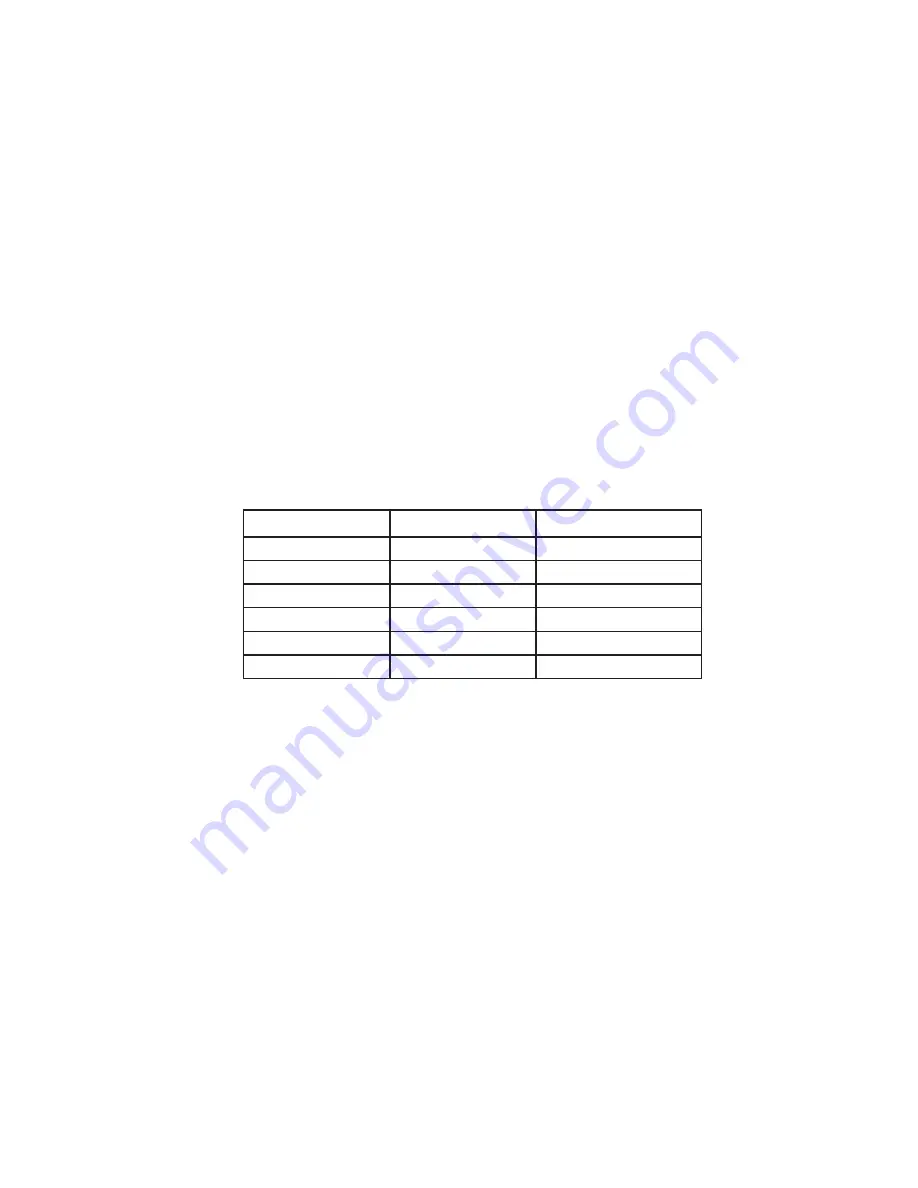
D. Harvest Control – Thermistor

A thermistor (semiconductor) is used for a harvest control sensor. The resistance varies 
depending on the suction line temperatures. The thermistor detects the temperature of 
the evaporator outlet to start the harvest timer. No adjustment is required. If necessary, 
check for resistance between thermistor leads, and visually check the thermistor 
mounting, located on the suction line next to the evaporator outlet.

Temperature (°F) 

Temperature (°C) 

Resistance (kΩ)

0

-18

14.401

10

-12

10.613

32

0

6.000

50

10

3.871

70

21

2.474

90

32

1.633

Check a thermistor for resistance by using the following procedure:

1) Disconnect the connector K3 on the board.
2) Remove the thermistor. See "V.I. Removal and Replacement of Thermistor."
3) Immerse the thermistor sensor portion in a glass containing ice and water for 

2 or 3 minutes.

4) Check for a resistance between thermistor leads. Normal reading is within 3.5 to 7 kΩ. 

Replace the thermistor if it exceeds the normal reading. 

Содержание KMD-901MAH

Страница 1: ...Hoshizaki A Superior Degree of Reliability www hoshizaki com Models KMD 901MAH KMD 901MWH KMD 901MRH Modular Crescent Cuber Hoshizaki America Inc SERVICE MANUAL Number 73154 Issued 3 28 2008...

Страница 2: ...intenance of the icemaker Should the reader have any questions or concerns which have not been satisfactorily addressed please call write or send an e mail message to the HOSHIZAKI Technical Support D...

Страница 3: ...nd Low Voltage Cut outs 18 f LED Lights and Audible Alarm Safeties 19 3 Controls and Adjustments 20 a Default Dip Switch Settings 20 b Harvest Timer S4 dip switch 1 2 20 c Pump Out Timer S4 dip switch...

Страница 4: ...Evacuation and Recharge R 404A 42 B Removal and Replacement of Compressor 43 C Removal and Replacement of Expansion Valve 44 D Removal and Replacement of Hot Gas Valve or Line Valve 45 E Removal and...

Страница 5: ...l Rear WEIGHT Net 240 lbs 109 kg Shipping 278 lbs 126 kg CONNECTIONS ELECTRIC Permanent Connection WATER SUPPLY Inlet 1 2 FPT DRAIN Outlet 3 4 FPT 5 8 OD Tube CUBE CONTROL SYSTEM Float Switch HARVESTI...

Страница 6: ...Net 219 lbs 99 kg Shipping 251 lbs 114 kg CONNECTIONS ELECTRIC Permanent Connection WATER SUPPLY Inlet 1 2 FPT Cond Inlet 1 2 FPT DRAIN Outlet 3 4 FPT Cond Outlet 3 8 FPT 5 8 OD Tube CUBE CONTROL SYS...

Страница 7: ...IC Permanent Connection WATER SUPPLY Inlet 1 2 FPT DRAIN Outlet 3 4 FPT 5 8 OD Tube CUBE CONTROL SYSTEM Float Switch HARVESTING CONTROL SYSTEM Hot Gas and Water Thermistor and Timer ICE MAKING WATER C...

Страница 8: ...8 B Condenser Unit 1 URC 9F Unit mm inches...

Страница 9: ...tion REFRIGERANT Discharge Line 1 1 16 12 UNF Fitting 10 AEROQUIP Liquid Line 5 8 18 UNF Fitting 6 AEROQUIP CONDENSER Air cooled Fin and tube type FAN MOTOR PROTECTION Thermal Protection REFRIGERANT C...

Страница 10: ...on 1 KMD 901MAH air cooled Control Box Spray Tubes Float Switch Water Pump Compressor Bin Control Drier Condenser Fan Motor Condenser Junction Box Hot Gas Valve Water Supply Inlet Expansion Valves Lin...

Страница 11: ...ter cooled Water Regulator Control Box Spray Tubes Float Switch Water Pump Compressor Bin Control Drier Condenser Junction Box Hot Gas Valve Water Supply Inlet Expansion Valves Line Valve Drain Valve...

Страница 12: ...H remote air cooled Receiver Tank Control Box Spray Tubes Float Switch Water Pump Compressor Bin Control Drier Junction Box Hot Gas Valve Water Supply Inlet Expansion Valves Line Valve Drain Valve Inl...

Страница 13: ...ength of harvest minus 50 seconds whichever is shorter LED 4 goes off when WV closes PM energizes and runs for the last 50 seconds of harvest LED 3 comes on when PM energizes At the end of harvest the...

Страница 14: ...harvest the control board checks the position of F S and proceeds to the freeze cycle if it is closed or calls for a 1 minute fill if it is open The unit continues to cycle through freeze and harvest...

Страница 15: ...4 Pump Out Cycle Cycle Steps Minimum freeze time 5 minutes Maximum freeze time freeze timer setting 5 minute timer in control F S in control Initial startup always begins here G board will have 5 sec...

Страница 16: ...due to static discharge It is especially important to touch the metal part of the unit before handling or replacing the board 3 Do not touch the electronic devices on the board or the back of the boar...

Страница 17: ...Hot Gas Valve HGV 3 Liquid Line Valve LLV 4 Pump Motor icemaking 5 Pump Motor harvest pump out 6 Inlet Water Valve WV 7 10 Supply Voltage 8 Open Switch for C board and ALPINE board service boards only...

Страница 18: ...sed with power on to reset the safety d Low Water Safety The control board checks the position of the float switch at the end of the initial one minute water fill cycle and at the end of each harvest...

Страница 19: ...main in the factory default position The built in safeties shut down the unit and have alarms as listed below No of Beeps every 3 sec Type of Alarm Notes 1 High Evaporator Temp temperature 127 F 53 C...

Страница 20: ...rmistor reads 48 F 9 C at the evaporator outlet No adjustment is required under normal use as the harvest timer is adjusted to the suitable position However a setting longer than the factory setting m...

Страница 21: ...ter Valve No 3 No 4 T1 T2 OFF OFF 10 150 closed ON OFF 10 180 closed OFF ON 10 120 open ON ON 20 180 closed T1 Time to drain the water tank T2 Harvest timer at pump out Depending on the pump out frequ...

Страница 22: ...S4 dip switch settings to assure that 3 4 7 8 9 10 are in the factory default position Switches 1 2 5 6 are cleaning adjustments and the settings are flexible Check the S5 dip switch settings to assu...

Страница 23: ...p switch 8 must remain off D Harvest Control Thermistor A thermistor semiconductor is used for a harvest control sensor The resistance varies depending on the suction line temperatures The thermistor...

Страница 24: ...chine to complete the freeze cycle and the following harvest cycle before shutting down the machine 2 Bin Control Check Procedure 1 Clear any ice away from the bin control 2 Move the control switch to...

Страница 25: ...25 III Technical Information A Water Circuit and Refrigeration Circuit 1 KMD 901MAH air cooled...

Страница 26: ...26 2 KMD 901MWH water cooled...

Страница 27: ...27 3 KMD 901MRH remote air cooled...

Страница 28: ...Diagrams 1 KMD 901MAH and KMD 901MWH Pressure Switch Air Cooled Model Water Cooled Model Cut out 412 21 3 PSIG 384 21 3 PSIG Cut in 327 21 3 PSIG 284 21 3 PSIG 0 0 Transformer Output 10 5V at 115V Se...

Страница 29: ...29 2 KMD 901MRH Pressure Switch Cut out 412 21 3 PSIG Cut in 327 21 3 PSIG 0 Transformer Output 10 5V at 115V Service Relay...

Страница 30: ...80 27 90 32 min 100 38 70 21 80 27 90 32 min 100 38 70 21 231 16 2 251 17 6 281 19 8 80 27 246 17 3 276 19 4 309 21 7 90 32 251 17 6 298 21 0 330 23 2 PSIG kg cm 2 G 100 38 258 18 1 306 21 5 360 25 3...

Страница 31: ...4 234 16 5 245 17 2 90 32 233 16 4 235 16 5 245 17 2 PSIG kg cm 2 G 100 38 237 16 6 237 16 7 254 17 9 70 21 38 2 7 39 2 7 41 2 9 80 27 38 2 7 39 2 8 43 3 1 90 32 39 2 7 40 2 8 44 3 1 PSIG kg cm2 G 100...

Страница 32: ...14 8 227 16 0 248 17 5 80 27 223 15 7 250 17 6 270 19 0 90 32 227 16 0 269 18 9 290 20 4 PSIG kg cm 2 G 100 38 231 16 2 274 19 3 309 21 7 70 21 36 2 5 38 2 7 43 3 1 80 27 38 2 7 41 2 9 47 3 3 90 32 3...

Страница 33: ...protection during initial start up and at the end of each harvest Diagnosis If the inlet water valve does not open check for no supply voltage at water valve terminals bad coil or plugged screen or ex...

Страница 34: ...pump out occurs after the 11th freeze cycle and every 10th cycle thereafter The pump out cycle can be adjusted to occur every cycle or every 2 5 or 10 cycles S4 dip switch 5 6 The compressor remains e...

Страница 35: ...ugged 6 Clean and replace drier 7 Condenser water pressure too low or off water cooled model only 7 Check and get recommended pressure g Transformer 1 Coil winding opened or shorted 1 Replace h Wiring...

Страница 36: ...ugh 3 to the right and d through f below 1 Loose terminal 1 Tighten or replace 2 Voltage 2 Check and correct 3 Dirty condenser 3 Clean d Starter 1 Bad contacts 1 Check and replace 2 Coil winding opene...

Страница 37: ...C 4 Control Board Check Procedure 8 All components run but no ice is produced a Refrigerant 1 Low charge 1 Check for leaks and recharge 2 Air or moisture trapped 2 Replace drier and recharge b Compre...

Страница 38: ...lace filter d Inlet Water Valve 1 Dirty mesh filter or orifice 1 Clean 2 Diaphragm does not close 2 Check for water leaks with icemaker off e Ambient and or water temperature 1 Too cool 1 Increase tem...

Страница 39: ...d condenser water regulating valve water cooled model only c Check pump hot gas valve headmaster C P R remote air cooled model only expansion valve refrigeration check valve and compressor 2 Harvest c...

Страница 40: ...ce 2 Fan blade deformed 2 Replace 3 Fan blade does not move freely 3 Replace c Compressor 1 Bearings worn out or cylinder valve broken 1 Replace 2 Mounting pad out of position 2 Reinstall d Refrigeran...

Страница 41: ...re with pressurized air for leak testing 1 Refrigerant Recovery The icemaker unit is provided with refrigerant access valves Using proper refrigerant practices recover the refrigerant from the access...

Страница 42: ...ge manifold to be used for evacuation and refrigerant charge should be exclusively for POE oils 2 Turn on the vacuum pump Open the service manifold valves Never allow the oil in the vacuum pump to flo...

Страница 43: ...ber grommets 6 Remove the discharge and suction pipes 7 Remove the compressor Unpack the new compressor package 8 Attach the rubber grommets of the prior compressor 9 Place the compressor in position...

Страница 44: ...Always protect the valve body by using a damp cloth to prevent the valve from overheating Do not braze with the valve body exceeding 250 F 121 C 8 Use an electronic leak detector or soap bubbles to c...

Страница 45: ...while purging with nitrogen gas flowing at a pressure of 3 to 4 PSIG CAUTION Always protect the valve body by using a damp cloth to prevent the valve from overheating Do not braze with the valve body...

Страница 46: ...bubbles to check for leaks Add a trace of refrigerant to the system if using an electronic leak detector and then raise the pressure using nitrogen gas 140 PSIG DO NOT use R 404A as a mixture with pr...

Страница 47: ...charge it with refrigerant See the nameplate for the required refrigerant charge 15 Connect the flare connections 16 Close the condenser water supply line drain valve then open the condenser water su...

Страница 48: ...Remove the drier then place the new drier in position 8 Braze all fittings with nitrogen gas flowing at a pressure of 3 to 4 PSIG CAUTION Always protect the headmaster body by using a damp cloth to p...

Страница 49: ...foam insulation thermistor holder and thermistor See Fig 2 6 Scrape away the old sealant on the thermistor holder and the suction pipe 7 Wipe off moisture or condensation on the suction pipe 8 Smooth...

Страница 50: ...nt of Inlet Water Valve or Drain Valve 1 Turn off the power supply 2 If replacing the inlet water valve close the icemaker water supply line shut off valve Open the icemaker water supply line drain va...

Страница 51: ...or overflow pipe Replace the insulation panel in its correct position 4 Disconnect the pump motor wiring connector 5 Disconnect the hoses attached to the pump motor assembly 6 Remove the two screws s...

Страница 52: ...ker 7 Lift off the insulation then remove the two thumbscrews attaching the bin control to the switch cover 8 Use the thumbscrews to attach the new bin control to the switch cover 9 Replace the remove...

Страница 53: ...uid proof gloves to prevent the cleaning and sanitizing solutions from coming into contact with skin 3 Carefully follow any instructions provided with the bottles of cleaning and sanitizing solution 4...

Страница 54: ...their correct positions Be careful not to cross thread the overflow pipe 7 In bad or severe water conditions clean the float switch as described below Otherwise continue to step 8 a Disconnect the ven...

Страница 55: ...tion 20 Turn on the power supply to fill the water tank with water 21 Turn off the power supply after 3 minutes 22 Remove the front panel and fully open the cleaning valve 23 Move the control switch t...

Страница 56: ...17 through 30 in 1 Cleaning Procedure two times to rinse thoroughly 12 Close the cleaning valve 13 Move the control switch to the ICE position 14 Replace the front panel in its correct position 15 Cl...

Страница 57: ...g temperatures 1 On water cooled model only first remove the water from the water cooled condenser 1 Turn off the power supply and remove the front panel and right side panel 2 Close the condenser wat...

Страница 58: ...ve cube guide A Remove the overflow cap overflow pipe and water shield See Fig 5 4 Remove the drain plug 5 Remove all ice from the storage bin dispenser unit Clean the storage bin dispenser unit using...

Отзывы: