HORNER ZX Series Скачать руководство пользователя страница 5

MAN0960-03-EN 


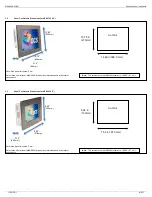
         Specifications / Installation


__________________________________________________________________________________________________________________________________________________________________________ 

11/30/2011                                                                                                                                                                                                                                                              #1037 


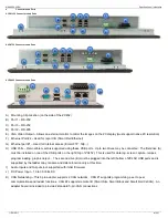
Port and Connector Pin-outs 


5.1 

CAN Network Port and Wiring 

 
6 Pin dual CAN connector  


 CAN 1 Port Pin Assignments 

Pin 

Signal 

Signal Description 

Direction 

#1 V-  

CAN #1 Ground - Black 


#1 CN_L 

CAN #1 Data Low - Blue 

In/Out 

#1 CN_H 

CAN #1 Data High-White 

In/Out 

 CAN 2 Port Pin Assignments


#2 V- 

CAN #2 Ground - Black 

#2 CN_L 

CAN #2 Data Low - Blue 

In/Out 

#3 CN_H 

CAN #2 Data High-White 

In/Out 

 
5 Pin CAN connector for Adapter Board 


NET Port Pin Assignments 

Pin 

Signal 

Signal Description 

Direction 

V- 

CAN Ground - Black 


CN_L 

CAN Data Low - Blue 

In/Out 

SHLD 

Shield Ground - None 


CN_H 

CAN Data High - White 

In/Out 

V+ (NC) 

No Connect - Red 


5.2 

Power Port and Wiring 


5.3 

Ethernet Port 


Speeds 

10 BaseT Ethernet (10-Mbps) 

100 BaseTx Fast Ethernet (100-Mbps) 

1000 Base Tx Fast Ethernet (1000-Mbps) 

Modes 

Half or Full Duplex 

Auto-Negotiation 

10/100/1000-Mbps and Half/Full Duplex 

Connector Type 

Shielded RJ-45 

Cable Type 
(Recommended) 

CAT5 (or better) UTP 

Port 

Auto MDI/MDI-X 


5.4 

Serial Ports 1, 2 and 3 


Serial Port 1&3 Pin Assignments RS-232 

Pin 

Signal 

Signal Description 

Direction 

CD 

Carrier Detect 


RX 

Receive 

IN 

TX 

Transmit 

OUT 

DTR 

Data Terminal Ready 


GND 

Ground 

DSR 

Data Set Ready 


RTS 

Ready to Send 


CTS 

Clear to Send 


RI 

Ring Indicate 


Serial Port 2 Pin Assignments RS-485 

Pin 

Signal 

Signal Description 

Direction 

TX/RX - 

Receive/Transmit - 

In/Out 

TX/RX + 

Receive/Tr 

In/Out 

NC 

Do Not Connect 

NC 

Do Not Connect 

GND 

Ground 

DSR 

Data Set Ready 


RTS 

Ready to Send 


CTS 

Clear to Send 


RI 

Ring Indicate 


5.5 

VGA Port 

 
The VGA port allows the items displayed on the internal display to be mirrored to an 
external display or projects.  The connector uses  standard analog VGA signaling and 
should work with a variety of monitors, displays and projects.  The external display should 
support the native resolution of the ZX unit. 
 

5.6 

USB Ports 

 
The ZX units have two (ZX351) or four (ZX751 & ZX1151) standard USB ports supporting 
high speed USB 2.0.  These ports will support external drives for data storage such as 
data logging, screen captures, program loading…  Drives larger than 2 gigabytes are 
supported and should be formatted with FAT-32.  Future firmware updates will allow 
other peripherals to be connected to these ports 


Technical Support 


For assistance and manual updates, contact Technical Support at the  
following locations: 


North America:   

Tel:  317 916-4274 
Fax: 317 639-4279 
Web:    

http://www.heapg.com


Email:  

[email protected]


Europe:  

Tel:  +353-21-4321266 
Fax: +353-21-4321826 
Web:    

http://www.horner-apg.com


Email:  

[email protected]


Pin 

Signal 

Description 

Ground 

Frame Ground 

V- 

Input Power Supply Ground 

V+ 

Input Power Supply Voltage 

CAN Connector 


Use the CAN Connector when 

using CsCAN network. 


Torque rating 4.5 – 7 Lb-In 

(0.50 – 0.78 N-m) 


Power Connector 


Power Up: 


Connect to Earth Ground. 

Apply 10 - 30 VDC. 

Screen lights up with slight delay. 


Torque rating 4.5 – 7 Lb-In 

(0.50 – 0.78 N-m) 


Содержание ZX Series

Страница 1: ...0 x 1080 Ladder Memory 1 MB 1 MB 1 MB Display Memory 130 MB 130 MB 130 MB Display Life 50 000 hours 25 C User Keys 5 virtual function keys 7 virtual function keys 7 virtual function keys Screens supported 1023 Colors 65536 Weight 3lb 1oz 1 39Kg 11lb 9oz 5 25Kg 18lb 3oz 8 25Kg CE UL Connectivity Serial 2 Ports 1 RS232 1 RS485 3 Ports 2 RS232 1 RS485 3 Ports 2 RS232 1 RS485 Ethernet 2 10 100 1000 1 ...

Страница 2: ...ght seal 5 Connect cables as needed such as communications programming power and CsCAN cables to the ports using the provided connectors 6 Begin configuration procedures Note The ZX1152 and ZX752 also supports standard VESA 75x75 or 100x100 mounting for wall or arm mounting The ZX452 supports the VESA 75x75 mounting pattern 4mm screws should be used and are typically supplied with the mount 3 1 Pa...

Страница 3: ...o the User Manual MAN0883 for panel box information and a checklist of requirements 3 3 Panel Cut Out and Dimensions for HE ZX452 7 Note Max panel thickness 5 mm Refer to the User Manual MAN0883 for panel box information and a checklist of requirements Note The tolerance to meet NEMA standards is 0 005 0 1 mm 3 15 80mm 15 75 400mm 12 60 320mm Cut Out 14 49 in 368 0 mm 10 75 in 273mm Note The toler...

Страница 4: ...FTP http H USB Ports Removable media is supported using these USB ports Up to two drives may be connected The first drive A must be installed on one of the USB ports on the right top of ZX452 This is used for data log screen capture recipes program loading graphic object The second drive B must be plugged into the left bottom of ZX452 USB ports and is supported by the ladder copy rename and delete...

Страница 5: ...ate Serial Port 2 Pin Assignments RS 485 Pin Signal Signal Description Direction 1 TX RX Receive Transmit In Out 2 TX RX Receive Transmit In Out 3 NC Do Not Connect 4 NC Do Not Connect 5 GND Ground 6 DSR Data Set Ready 7 RTS Ready to Send 8 CTS Clear to Send 9 RI Ring Indicate 5 5 VGA Port The VGA port allows the items displayed on the internal display to be mirrored to an external display or proj...

Страница 6: ...nuals in their entirety before proceeding Failure to observe this precaution could result in severe bodily injury or loss of life All applicable codes and standards need to be followed in the installation of this product Adhere to the following safety precautions whenever any type of connection is made to the module Connect the safety earth ground on the power connector first before making any oth...

Отзывы: