background image

21

E-flite DHC-2 Beaver ARF Assembly Manual



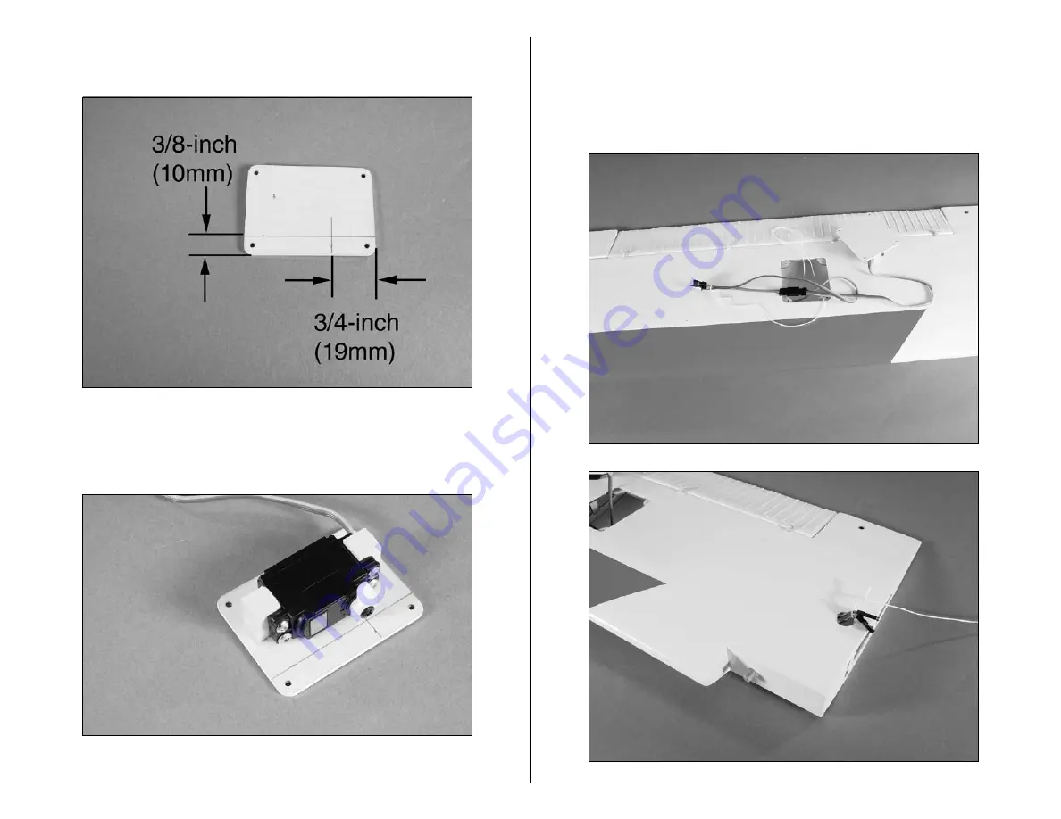
  15. Using a ruler, mark the servo cover as shown  

using a pencil.



  16. Repeat Steps 1 through 6 to attach the flap servo to 

the servo cover. Align the servo arm on the intersection of 

the lines drawn in the previous step.



  17. Secure a 3-inch (76mm) extension to the flap servo 

lead. Tie the string to the flap servo extension and pull 

both the aileron and flap leads to the hole in the bottom 

of the wing. Use tape to keep the leads from falling back 

into the wing.

Содержание E-flite PLATINUM DHC-2 Beaver ARF

Страница 1: ...Specifications Wingspan 68 in 1735mm Length 43 in 1090mm Wing Area 565 sq in 36 4 sq dm Weight w Battery 4 9 6 2 lb 2 2 2 8 kg Weight w o Battery 4 4 25 oz 1 8 1 9 kg DHC 2 Beaver ARF Assembly Manual ...

Страница 2: ... For anyone looking for an authentic looking replica of a durable utility plane with amazing scale detail that is easy to assemble the Beaver is the sport utility vehicle of aircraft Platinum Series Statement Our Platinum Series delivers superior enhanced features and meticulous attention to detail The symbol on this kit is your assurance of excellence and one more way that E flite brings you the ...

Страница 3: ...ircle are performed once while steps with two circles indicate that the step will require repeating such as for a right or left wing panel two servos etc Remember to take your time and follow the directions Contents of Kit Parts Layout Large Parts EFL4526 Wing Set EFL4527 Fuselage EFL4528 Tail Set Small parts EFL4529 Cowling EFL4530 Window Set EFL4531 Landing Gear EFL4532 Battery Hatch EFL4533 Pus...

Страница 4: ...UL UltraLite 7 Channel ScanSelect PCM Receiver 72MHz Or SPMAR6200 AR6200 DSM2 6 Channel Receiver UltraLite for DX6i on DX7 Or SPM6070 AR7000 DSM2 7CH Rx for DX6i or DX7 And JSP20040 MN48 Mini Servo 6 JSP98100 3 inch Servo Extension 2 JSP98020 6 inch Y Harness 2 JRPA096 9 inch Servo Extension JSP98030 12 inch Servo Extension 2 Important Information About Motor Selection We recommend the E flite Pow...

Страница 5: ...ase Separately EFLA257 Screwdriver 1 and 2 Phillips or included with EFLA250 EFLA251 Hex Wrench 3 32 inch or included with EFLA250 6 minute epoxy Canopy glue Covering iron Drill Drill bit 1 16 inch 1 5mm 5 64 inch 2mm 1 8 inch 3mm Felt tipped pen Flat blade screwdriver Hobby knife 11 blade Low tack tape Medium CA Pencil Phillips screwdriver 1 2 Pin drill Rotary tool w sanding drum Ruler Sandpaper ...

Страница 6: ...ty a This warranty is limited to the original Purchaser Purchaser and is not transferable REPAIR OR REPLACEMENT AS PROVIDED UNDER THIS WARRANTY IS THE EXCLUSIVE REMEDY OF THE PURCHASER This warranty covers only those Products purchased from an authorized Horizon dealer Third party transactions are not covered by this warranty Proof of purchase is required for warranty claims Further Horizon reserv...

Страница 7: ... Your local hobby store and or place of purchase cannot provide warranty support or repair Once assembly setup or use of the Product has been started you must contact Horizon directly This will enable Horizon to better answer your questions and service you in the event that you may need any assistance For questions or assistance please direct your email to productsupport horizonhobby com or call 8...

Страница 8: ...e following address Horizon Product Support 4105 Fieldstone Road Champaign Illinois 61822 Please call 877 504 0233 with any questions or concerns regarding this product or warranty Safety Precautions and Warnings As the user of this product you are solely responsible for operating it in a manner that does not endanger yourself and others or result in damage to the product or the property of others...

Страница 9: ...be installing floats on your DHC 2 Beaver you can skip to the next section to install the motor and battery 1 Check the fit of the landing gear in the fuselage Note that there is a right and left landing gear assembly 2 Secure the left half of the landing gear using two 6 32 x 3 8 inch socket head screws and two 6 washers Use a 7 64 inch ball driver to tighten the screws Note Make sure to use thre...

Страница 10: ... Power 32 specific 4 40 x 1 inch socket head screw 4 Aluminum motor spacer 4 Power 25 specific 4 40 x 1 2 inch socket head screw 4 Required Tools and Adhesives Ball driver 3 32 inch Threadlock Phillips screwdriver 1 2 6 minute epoxy Note Standard wheel version We flew the prototype Beavers on Power 25 s and 3S Li Po systems with plenty of power for basic maneuvers and flight performance Float vers...

Страница 11: ... the screws using a 3 32 inch ball driver Make sure to use threadlock on the four screws to prevent them from vibrating loose 2b Attach the Power 25 motor to the firewall using four 4 40 x 1 2 inch socket head screws and four 4 washers Tighten the screws using a 3 32 inch ball driver Make sure to use threadlock on the four screws to prevent them from vibrating loose Note The blind nuts in the fuse...

Страница 12: ...th the operation of the motor 5 Use a hobby knife and rotary tool to remove the area in the center of the dummy radial engine Use a hobby knife to remove the area between each of the cylinders to allow cooling air to pass through the cowling and over the motor Use 6 minute epoxy to glue the dummy radial engine inside the cowling Use the following colors to paint the dummy radial engine Note We use...

Страница 13: ...ced propeller may strip the gears or cause poor flight characteristics Note If it is necessary to enlarge the hole in the propeller make sure to check the balance of the propeller afterwards Note Some DHC 2 beaver s utilized a spinner and some did not We have included a spinner for you if you so wish to use one On the model we have represented we did not use a spinner we used only a prop nut 7 Ins...

Страница 14: ...t the rear with two magnets To open the hatch insert your thumb and index finger into the cups and pinch towards the middle of the hatch Then lift towards one side to release one magnet and then pull up and away from the model to release the second model Note If you are not flying with floats you may wish to cut the plastic cups out of the hatch and make two holes for your fingers If you intend to...

Страница 15: ...essary You may also wish to use some hook and loop tape on the tray to secure the battery from sliding fore or aft 12 You may elect to cut a hole for exit air in the aft area of your fuselage You will notice we have designed the structure so that an air exit hole may be located in the following position Using the batteries listed in this manual we found no need for an air exit hole in the fuselage...

Страница 16: ...2 2 x 3 8 inch sheet metal screw 16 Required Tools and Adhesives Thin CA Pin drill Drill Side cutters Phillips screwdriver 1 Pencil String Ruler Low tack tape 6 minute epoxy Drill bit 1 16 inch 1 5mm 5 64 inch 2mm mmm 1 Position the aileron servo on the servo cover so the arm is centered lengthwise in the cutout The arm will align with the edge of the servo cover as well Use a pencil to mark the p...

Страница 17: ... The servo should not touch the cover to prevent it from absorbing vibrations from the airframe You may have to notch the servo block to allow access for the servo wire mmm 4 Use a drill and 1 16 inch 1 5mm drill bit to drill the holes for the servo mounting screws mmm 5 Apply a few drops of thin CA to each of the holes drilled in the previous step to harden the surrounding wood ...

Страница 18: ...servo mounting blocks m 7 Remove any of the unnecessary arms from the servo horn using side cutters Enlarge the outer hole of the servo arm with a pin drill and 5 64 inch 2mm drill bit m 8 Secure a 9 inch 228mm servo extension to the aileron servo Use string or a commercially available connector to keep them from unplugging inside the wing accidentally ...

Страница 19: ...to the opening for the flap servo at this time m 10 Secure the aileron servo cover to the wing using four 2 x 3 8 inch sheet metal screws and a 1 Phillips screwdriver m 11 Slide the bend of the 2 3 16 inch 56mm pushrod into the hole of the aileron servo Secure the pushrod using the pushrod connector ...

Страница 20: ...rvos for installation by removing any unnecessary arms from the servo horns as shown You will also need to clean up the cuts to prevent any portion of the removed arm from rubbing against the servo cover when the servos are installed Install any grommets and brass eyelets at this time as well The servos will have the arms installed to match each other as shown in the photo Note The arms are shown ...

Страница 21: ...e flap servo to the servo cover Align the servo arm on the intersection of the lines drawn in the previous step m 17 Secure a 3 inch 76mm extension to the flap servo lead Tie the string to the flap servo extension and pull both the aileron and flap leads to the hole in the bottom of the wing Use tape to keep the leads from falling back into the wing ...

Страница 22: ...e of the flap servo Secure the pushrod using the pushrod connector Slide a clevis retainer onto a nylon clevis Thread the clevis onto the pushrod m 19 Position the flap servo partially in the wing Connect the clevis to the flap control horn Plug the flap servo into the receiver and power up the radio system ...

Страница 23: ...on move the control on the radio to the Up Flap position and test fit the cover If the cover does not fit without binding the flap or flap servo adjust the length of the linkage or change the end points at the radio system to eliminate any binding Repeat the process for Down Flap and check that the full throw is adjusted as noted in the Control Throw section of this manual m 21 Secure the flap ser...

Страница 24: ...1 Mark the wing joiner and the wing panels so the joiner can easily be positioned consistently during the joining of the wings 2 Slide the wing joiner into the wing panel Use a pencil to mark the joiner against the wing The joiner should fit snug in the wing If it does not fit lightly sand the joiner until it does fit nicely 3 Slide the joiner into the opposite wing panel It should slide in to sli...

Страница 25: ...f the steps if you are unsure of the procedure 4 Mix up some 30 minute epoxy and apply it to one half of the joiner Make sure to coat the top bottom and both sides of the joiner 5 Coat the root rib of the wing panel with epoxy Apply epoxy into the opening for the joiner as well 6 Slide the joiner into the wing panel Apply epoxy to the joiner and to the wing as described in Step 5 and slide the two...

Страница 26: ... panels tightly together until the epoxy fully cures Note You may use rubbing alcohol and paper towels to clean up any epoxy that might have spilt on the wings during this process before the epoxy hardens 8 Using a trim iron iron on the piece of white ultra cote to seal the wing joint ...

Страница 27: ...in CA Hobby knife w new 11 blade Square Threadlock Sandpaper Hex wrench included with kit 1 Use a 1 Phillips screwdriver to remove the four screws holding the tail cone in position Set the screws aside in a safe location at this time 2 Attach the wing to the fuselage using a flat blade screwdriver and the two nylon wing bolts 3 Attach the wing struts to the wing and fuselage using two 2 x 3 8 inch...

Страница 28: ...ments must be equal If not reposition the stabilizer until both measurements are equal A A A A 6 Check the alignment between the wing and stabilizer They should be parallel to each other If not lightly sand the stabilizer saddle until the wing and stabilizer are in alignment with each other Parallel 7 Once the tail of your Beaver has been aligned use a felt tipped pen to trace the outline of the f...

Страница 29: ... flight Note You can use a soldering iron instead of a knife This will eliminate the chances of cutting into the wood 9 Slide the stabilizer back into position After checking the alignment wick thin CA into the joint between the fuselage and stabilizer on both the top and bottom of the stabilizer Also wick thin CA into the surrounding wood on the bottom of the fuselage to increase the bond between...

Страница 30: ...sert the rudder control rod into the fuselage then slide the fin into the slot in the top of the fuselage 11 Use a felt tipped pen to trace the outline of the fuselage onto the fin Also trace the outline of the dorsal fin onto the top of the fuselage ...

Страница 31: ...ying wood as this will weaken the fin and cause it to fail in flight Also trim the covering on the top of the fuselage 13 Check that the fin is square to the stabilizer Sanding the bottom of the fin where it fits into the fuselage can correct for any alignment issues A slight amount of material from the bottom of the fin might need to be removed for a correct fit ...

Страница 32: ...to use threadlock to ensure this assembly does not come apart during flight Note Do not mix up the rudder and tail wheel control horns They are packaged separately as they are not interchangeable 15 Wick thin CA into the joint between the fuselage and fin Make sure the fin is glued into the slot in the fuselage as well as to the top of the fuselage Note If you are installing floats please continue...

Страница 33: ...1mm pushrod wire 25 7 8 inch 658mm pushrod wire Required Tools and Adhesives Pin drill Thin CA Drill bit 1 16 inch 1 5mm 5 64 inch 2mm Phillips screwdriver 1 Side cutters m 1 Install the grommets and brass eyelets for the rudder servo Use a pin drill and 5 64 inch 2mm drill bit to enlarge the outer holes right and left of the servo arm m 2 Remove the two arms front and rear from the servo horn usi...

Страница 34: ... the rudder control horn as shown The pushrod and brass connector will be on the same side of the servo horn 5 Repeat Steps 1 and 2 to prepare the elevator servo m 6 Place the elevator servo into the fuselage with the output facing to the front Use a pin drill and 1 16 inch 1 5mm drill bit to drill the holes for the servo mounting screws ...

Страница 35: ...he surrounding wood This hardens the wood and provides a better bite for the screws m 8 Install the elevator servo using the screws provided with the servo 9 Repeat Steps 6 through 8 to install the rudder servo 10 Slide the 23 7 8 inch 606mm pushrod wire into the tube inside the fuselage for the rudder pushrod ...

Страница 36: ...Slide the clevis retainer over the clevis to prevent the clevis from opening and becoming disconnected from the rudder control horn m 13 Slide the pushrod into the hole in the servo horn and secure it using a pushrod connector m 14 Plug the rudder servo into the radio system and check the operation of the rudder servo Center both the rudder stick and trim Adjust the clevis to center the rudder whi...

Страница 37: ... installing floats skip Steps 16 and 17 as they pertain to the installation of the tail wheel linkage 16 Place a clevis retainer on a nylon clevis and thread the clevis on the remaining pushrod wire Slide the wire into the pushrod tube inside the fuselage and through the pushrod connector of the rudder servo Secure the clevis to the tail wheel control horn ...

Страница 38: ...od Use this connection to trim the steering of your Beaver on the ground DO NOT use the radio trim to correct the steering trim Note Your kit will use a 3mm setscrew instead of the machine screw shown in the photo 18 Install the tail cone using the screws that were removed earlier in the manual and a 1 Phillips screwdriver ...

Страница 39: ... assembly Float set w hardware Beaver float mount included with kit Landing gear plug 2 Required Tools and Adhesives Drill Thin CA String Threadlock Phillips screwdriver 2 Silicone adhesive Hex wrench included with kit Drill bit 5 64 inch 2mm 1 8 inch 3mm Note The hardware used to mount the floats and struts to your Beaver is from the E flite float set EFLA500 1 Install the float mount braces betw...

Страница 40: ...s aganst the surface will help keep everything in alignment while tightening the setscrews Only tighten the setscrews hand tight at this point m 3 Position the strap for the float mount at the corner of the battery tray as shown It should be as close as possible to the battery hatch yet not prevent the hatch from opening Use a drill and 5 64 inch 2mm drill bit to drill the holes for the front moun...

Страница 41: ...t Steps 3 and 4 for the rear mounting straps The main concern is the float mount is centered side to side on the bottom of the fuselage 6 Using threadlock tighten the setscrews for the cross braces on the float mount Assemble and attach the floats to the float mounts using the instructions provided with your float set The float with the water rudder installs on the left side of the model ...

Страница 42: ...A to glue the landing gear plugs to the fuselage at this time as well You may also opt to use clear tape to install the landing gear plugs in the fuselage if you might change from floats to wheels from time to time 8 Connect the pushrod cable to the connector The pushrod must be secured inside the fuselage Wrap string around the pushrod tube and the cross member of the radio tray Soak the string w...

Страница 43: ...lue Hobby scissors Hobby knife Low tack tape Optional tools Drill Drill bit 5 64 inch 2mm Phillips screwdriver 1 Medium CA Note If you are not installing the optional cockpit perform Steps 4 5 7 11 and 12 1 Use medium CA to secure the instrument panel in position as shown 2 Test fit the forward cockpit floor in the fuselage Trim the floor as necessary using hobby scissors The cockpit floor is then...

Страница 44: ...t backs Attach the seat backs to the forward cockpit floor 4 Trim the forward side windows from the window set using hobby scissors and a hobby knife 5 Use canopy glue to secure the right and left front side windows to the inside of the fuselage 6 Use medium CA to secure the pilot twins to the forward cockpit floor ...

Страница 45: ...e sandpaper to provide a surface for the adhesive to bond to 8 Use medium CA to glue the rear cockpit floor blocks to the sides of the fuselage slightly below the level of the center side window There will be two blocks on each side of the fuselage as shown 9 Remove the backing from the adhesive strips on the bottom of the seat backs Attach the seat backs to the rear cockpit floor ...

Страница 46: ...s will go through the rear cockpit floor and into the block installed in Step 8 Route the leads for the flaps and ailerons from underneath the floor at this time 11 Trim the center and rear side windows from the window set using hobby scissors and a hobby knife 12 Use canopy glue to secure the remaining side windows to the inside of the fuselage ...

Страница 47: ...t the transmitter if necessary 2 Check the movement of the elevator with the radio system Moving the elevator stick down will make the airplane elevator move up 3 Check the movement of the ailerons with the radio system Moving the aileron stick right will make the right aileron move up and the left aileron move down 4 Use a ruler to adjust the throw of the elevator ailerons and rudder Adjust the p...

Страница 48: ...measured from our own flight tests You can experiment with higher rates to match your preferred style of flying Once all the control throws have been set make sure to slide the clevis retainers over the clevises to prevent them from opening accidentally Range TestYour Radio 1 Please consult your radio instructions for complete range testing instructions 2 Double check that all controls aileron ele...

Страница 49: ...uld be charged the night before going out flying Before each flying session be sure to range check your radio See your radio manual for the recommended range and instructions for your radio system Each radio manufacturer specifies different procedures for their radio systems Next start the motor With the model securely anchored check the range again The range test should not be significantly affec...

Страница 50: ...e We at E flite hope you enjoy your Beaver as much as we have Happy landings FlyingYour DHC 2 Beaver ARF You will find the Beaver to be a very docile model in the air and on the ground Takeoff s are a piece of cake with the large rudder and flaps Landings are slow and gentle with the large flap area fully deployed on final approach Begin by placing the model on the ground Check all control throws ...

Страница 51: ...e established in front of which all flying takes place with the other side for spectators Only personnel involved with flying the aircraft are allowed at or in front of the flight line Intentional flying behind the flight line is prohibited 4 I will operate my model using only radio control frequencies currently allowed by the Federal Communications Commission Only properly licensed Amateurs are a...

Страница 52: ...12403 1 2008 Horizon Hobby Inc 4105 Fieldstone Road Champaign Illinois 61822 877 504 0233 horizonhobby com E fliteRC com ...

Отзывы: