

311-0288- 277 Rev
B
2/13 © 2013 Hopkins Manufacturing
Corporation
Pro Quip International
14 London Drive
Bayswater 3153 VIC
Ph: (03) 9761 1110
Email: [email protected]
www.proquip.com.au
LIMITED LIFETIME WARRANTY
Hopkins Manufacturing Corporation warrants I
N
S
IGHT
™
, Agility
™
,
Reliance
™
,
B
rake-Force
™
and Impulse
™
brake control products to be free
from defects in material and workmanship, under normal use and
service, for the original buyer
’
s lifetime from the date of original
purchase.
This warranty does not cover, and Hopkins Manufacturing Corporation
is not liable for, the cost of repair or replacement of parts which have
been subjected to misuse, negligence, accident, improper installation,
mod
ifi
cation, or normal deterioration due to wear and exposure, or
defects caused by unauthorized repairs.
THE ORIGINAL
BU
YE
R’S
EXCL
US
IVE REMEDIE
S
U
NDER THI
S
LIMITED
WARRANTY
S
HALL
B
E LIMITED TO REPAIR OR REPLACEMENT (AT THE
OPTION OF HOPKIN
S
MA
NU
FACT
U
RING CORPORATION) OF THE
DEFECTIVE PRO
DUC
T OR PART.
The repair or replacement of the product or part under warranty will be
made by Hopkins Manufacturing Corporation without charge for parts
or labor.
U
NDER NO CIRC
U
M
S
TANCE
S
WILL HOPKIN
S
MA
NU
FACT
U
RING
CORPORATION
B
E LIA
B
LE FOR INCIDENTAL OR CON
S
EQ
U
ENTIAL
DAMAGE
S
, INCL
U
DING
BU
T NOT LIMITED TO DAMAGE TO OR LO
SS
OF
OTHER PROPERTY OR EQ
U
IPMENT.
S
ome states do not allow the exclusion or limitation of incidental or
consequential damages, so the above limitations or exclusions may not
apply to you. This warranty gives you spec
ifi
c legal rights, and you may
also have other rights which vary from state to state.
In order to obtain performance under this warranty, return the defective
product, postage prepaid, along with dated proof of purchase, to
Hopkins Manufacturing Corporation, 42
8
Peyton, Emporia, Kansas
668
01-1157. This warranty does not cover shipping and delivery charges
to or from Hopkins Manufacturing Corporation.
BRAKE CONTROL
WIRE COLOR
BLACK
RED
WHITE
BLUE
MAKE
MODEL
& YEAR
CHEVY
& GMC
2007
(New
Style)
- 2013
RED
LIGHT
BLUE &
WHITE
WHITE
DARK
BLUE
CHEVY
& GMC
1999 - 2007
(Classic Style)
RED
LIGHT
BLUE
BLACK
DARK
BLUE
DODGE
2009-2012
RED &
YELLOW
WHITE &
VIOLET
BLACK &
DRK GREEN
DARK
GREEN
DODGE
2003-2008
RED &
WHITE
BLUE &
WHITE
BLACK &
GREEN
BLUE
DODGE
1997-2002
RED
WHITE
BLACK
BLUE
FORD
F-250 / 350
2009-2013
RED &
BROWN
BLUE
ORANGE
BLACK &
GRAY
BLUE
FORD
F-150 2009-
2013
RED OR
RED &
GRAY
GREEN
OR YEL
GRN
WHITE &
BROWN
BLUE
FORD
F-150
1994-2008
RED
LIGHT
GREEN
WHITE
DARK
BLUE
TOYOTA
&
LEXUS
2003-2012
BLACK
GREEN &
YELLOW
BLACK &
WHITE
BLUE &
RED
VEHICLE WIRE COLOR
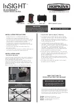
TESTING / ADJUSTING
THE BRAKING RESPONSE:
Connect to your trailer and test drive on a dry open area at low speed (30 to
40 kph). Apply vehicle brakes aggressively.
1. If trailer brakes lock-up, adjust down the power setting to just below brake
lock-up by pressing the (-) power button.
2. If the braking performance from the trailer feels as if it is pushing the tow
vehicle, adjust the power setting higher by pressing the (+) power button.
Repeat process until smooth braking is obtained.
1. RED DOT
A red dot on bottom-right hand corner of the digital
display indicates trailer is connected.
2. BLANK
A blank display (no dot) indicates trailer is not
connected.
3. POWER
Power adjustment buttons (+/-) on top of the control
adjust power sent to the trailer brakes. Pressing the (-)
button decreases power. Pressing (+) increases
power. Power will be displayed as a percentage on the
digital display from 5 to 99 in increments of 5%.
4. SENSITIVITY
This feature makes your trailer braking response more
or less sensitive. A setting of 1 indicates least
sensitive. A setting of 7 indicates most sensitive.
Adjust the sensitivity by pressing the button labeled
“S” on the side of the unit.
5. SHORT CIRCUIT
SC indicates that a short circuit has occurred.
(blank)
OPERATING AND SETTING
YOUR CONTROLLER
NOTES
• Some late model Ford/Mercury trucks and sport utility vehicles have 2 or
more stop lamp switch wires. For proper operation, use the light green wire.
The other wire is red with a green stripe. This wire goes directly to ground
when not in use. Splicing into this wire will short circuit your brake control
and possibly damage the unit.
• For Chevrolet vehicles 1999-06, if your vehicle does not have a towing
package, only the ground and stop lamp switch will be active in the function
wires under the dash. The electric brake wire and 12-volt power lead will be
terminated outside the firewall. These will have to be routed to the trailer
connector and battery on the vehicle.
• For Chevrolet vehicles 2007 New Body Style-13, only the ground and stop
lamp switch will be active in the function wires under the dash. The electric
brake wire and 12-volt power lead will be terminated outside the firewall.
These will have to be routed to the fuse block on the vehicle. 20-amp fuses
will need to be installed to power these functions.
• For Dodge 2005-06, to find the cold side of the stop lamp switch, you must
have the key in the “on” position.
• Ford and Dodge tow packages come with a 20-amp battery feed wire
system that will accommodate 2 and 4 brake trailer magnets. An upgrade to
a 30-amp (12 gauge) battery wire system will be needed for 6 brake
systems.
VEHICLE MANUFACTURER
WIRING CODES
For installations on vehicles
WITHOUT
a factory tow
package use the following procedure:
1. Be sure to use proper wire gauge when installing your control (12 gauge for
electric brakes and positive power, 16 gauge for the stop lamp switch and
ground).
2. Connect the white wire directly to the negative post on the vehicle battery.
Grounding to any other location may cause intermittent brake control
operation or failure.
3. Attach 20-amp circuit breaker (for 6 or 8 brake use 30-amp) or in-line fuse
to the positive terminal on the vehicle’s battery. Route black wire from the
brake control to the fuse or breaker.
4. Splice the red wire into the cold side of the vehicle’s stop lamp switch
located by the brake pedal. Find the wire by using a circuit tester and
probing for the wire that powers the vehicle stop lamps when the brake
pedal is pressed.
5. Route the blue wire from the brake control to the vehicle side towing
connector at the rear of the tow vehicle.


