


S
OUNDTRACK
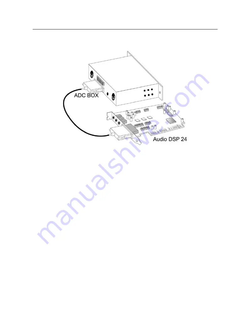
Audio DSP24
- 11 -
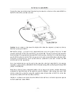
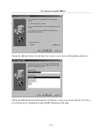
Connect the long cream 44-pin lead from the 44-pin connector on the rear of the Audio DSP24 to
the DATA Out of the external converter.
Caution:
never connect or disconnect the 44pin cable when the computer is turned on. Always
shot down your system before.
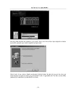
DIP Switch settings - you need to have
one
DIP switch in the UP position. There are 10 DIP
switches on the side of the each external box (except DAC III). The down position represents OFF
for all switches. The up position represents ON for all switches. Switches 1-4 set the units unique
specific ID for software control. This is necessary so the system can differentiate individual ADC
converters or external boxes, when several units are connected to one card. At least one DIP
switch must be in the up position.
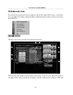
Up to four external devices can be used at the same time with the Audio DSP 24. An example
would be a system with the ADC&DAC2000 (8 channel analog I/O) and the Digital Station 2000
(ADAT and TDIF I/O).
Remember, each box needs a unique ID number. If you connect a second box, the Box ID number
controlled by the DIP switch on the right side must be different. After setting the correct DIP
switch, connect the second box using the supplied cream 44-pin cable to DATA In of the first
external box and the DATA Out of the second one.
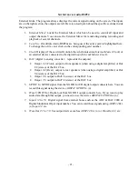
Chapter X. contains more details about the different external boxes and other expansion options
for the SoundTrack Audio DSP24.


