


Honeywell Process Solutions
Wireless Dual Analog Input Interface Transmitter
30
User Manual
Rev. 8
July 2012
Each Transmitter is equipped with an analog input level upper and lower
value. As the analog input is measured, it is compared to a set threshold
value. Depending upon the setting of that value, whether it is enabled or
not, and what the Time Deadband is, the Transmitter will enter an Abnor-
mal condition as seen in Figure 6.14.
The Normal Upper Value would be an indication that the analog input is
‘high’ and the Normal Lower Value would be an indication that analog
input is ‘low’. Thus the normal operating condition for the analog input
application would be found in between the two Normal Values.
The Time Deadband refers to the number of seconds that the measured
reading must stay in a certain condition before the Transmitter will actu-
ally switch to that condition. To select a proper Time Deadband consider
the example in Figure 6.15.
Notice that the Transmitter continues to cycle from Normal to Abnormal
Conditions due to the fact that the input value is fluctuating around the 7.5
Volt Normal Upper Value. This is undesired. The addition of a few second
delay before the Transmitter switches conditions will eliminate this
“chatter”, as seen in Figure 6.16.
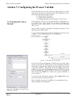
6.6: Selecting the Normal Up-
per and Lower Values*
* Indicates that Menu is Disabled if Wireless Management Toolkit is detected. (See Appendix A)
Figure 6.14: Normal Upper and Lower
Value Example
Figure 6.16: Condition “Chatter” Elimina-
tion Due to Time Deadband
Figure 6.15: Condition “Chatter” Without
Time Deadband
Using Wireless Management Toolkit
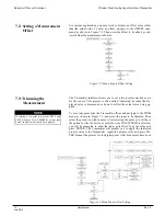
6.6.1: Configure the Upper and
Lower Limits from the Transmitter*
The Upper and Lower Limits cannot be configured on Dual Analog Input
Transmitters. The Upper and Lower Limits can only be enabled using
WMT.
If you have the Wireless Management Toolkit software this menu option
will not be accessible via the Transmitter once the Transmitter detects
that the software is being used (See Appendix A for more details). An
explanation of how to select the Abnormal Sampling Rate using the
Wireless Management Toolkit software can be found in section 6.7.
Содержание XYR 5000 Series
Страница 2: ......
Страница 46: ...Honeywell Process Solutions Wireless Dual Analog Input Interface Transmitter 40 User Manual Rev 8 July 2012 ...
Страница 47: ...Honeywell Process Solutions Wireless Dual Analog Input Interface Transmitter Rev 8 User Manual 41 July 2012 ...
Страница 48: ...Honeywell Process Solutions Wireless Dual Analog Input Interface Transmitter 42 User Manual Rev 8 July 2012 ...
Страница 49: ...Honeywell Process Solutions Wireless Dual Analog Input Interface Transmitter Rev 8 User Manual 43 July 2012 ...
Страница 50: ...Honeywell Process Solutions Wireless Dual Analog Input Interface Transmitter 44 User Manual Rev 8 July 2012 ...