background image

COMPACT I/O MODULE

3

95-7717—2

TERMINATION

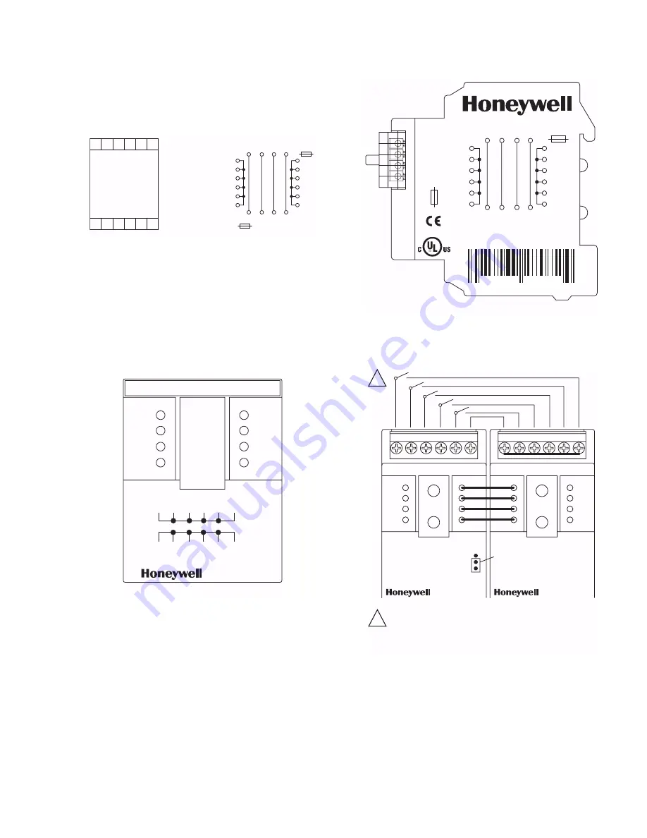
Fig. 1 shows the termination points of the XIO-10HUB.

Fig. 1. Termination diagram for XIO-10HUB.

WIRING

Wiring of the XIO-10HUB must be accomplished in 

accordance with federal, state, and local requirements.  

Figures 2 through 4 show sample diagrams of wiring for the 

XIO-10HUB.

Fig. 2. Front panel diagram of XIO-10HUB.

Fig. 3. Side panel diagram of XIO-10HUB.

Fig. 4. Wiring example XIO-10HUB used with XIO-10DI.

M25039

1

7

2

8

3

9

4

10

5

11

6

12

+24 V

GND

E1
E2

+24 V

GND

E1
E2

E2

E1 GND +24V

E2

E1 GND +24V

7

8

9

10

11

12

1

2

3

4

5

6

BUS

Ub

10 A

Max. 60 V

Bus-Stecker max. 3 A

M25071

+24V

24V

GND

E1
E2

+24V

24V

GND

E1
E2

+24V

GND

1

7

2

8

3

9

4

10

5

11

6

12

XIO-10HUB

M25072A

E2 E1 GND +24V

7

8

9

10

11

12

1

2

3

4

5

6

BUS

Ub

10 A

Max. 60V

Bus-Plug max. 3A

E2 E1 GND +24V

XIO-10HUB

0

4

8 5 2 6 7 2 7 0 7 2

1

1

Each switch has two 14 AWG (2.5 mm

2

) connectors.

NOTE: ADDITIONAL WIRING POINTS, ONLY ONE WIRE /

CONNECTOR; ALSO FOR RELAY OUTPUT.

M25073

+24V

24V

GND

E1
E2

+24V

24V

GND

E1
E2

XIO-10DI

10

9

8

7

6

C

+24V

24V

GND

E1
E2

+24V

24V

GND

E1
E2

XIO-10HUB

1

2

3

4

5

6

10

1

9
2

8
3

7
4

6
5

SERVICE

ON

Jumper

Содержание XIO-10HUB

Страница 1: ...y Construction Material Housing and Terminal Blocks Polyamide 6 6 V0 Faceplate Polycarbonate Protection IP40 housing DIN 40050 IP20 terminal blocks DIN 40050 Approvals UL 916 Standard for Energy Management Equipment European Community Mark CE Listed SAFETY INSTRUCTIONS NOTES REGARDING DEVICE DESCRIPTION These instructions include indications for use and mounting of the device In case of questions ...

Страница 2: ... stranded wires c Insert the wire to the respective contact and secure it by screwing down the contact screw d Wire cross section of the 4 pole terminal block bus mains connection 1 Maximum 16 AWG 1 5 mm2 single wire 2 Maximum 18 AWG 1 0 mm2 stranded wire 3 Wire diameter minimum 28 AWG 0 3 mm up to 16 AWG 1 4 mm 4 Prepare cable for module connections a Strip the wires by 0 3 in 7 mm Put a wire end...

Страница 3: ... 3 9 4 10 5 11 6 12 24 V GND E1 E2 24 V GND E1 E2 E2 E1 GND 24V E2 E1 GND 24V 7 8 9 10 11 12 1 2 3 4 5 6 BUS Ub 10 A Max 60 V Bus Stecker max 3 A M25071 24V 24V GND E1 E2 24V 24V GND E1 E2 24V GND 1 7 2 8 3 9 4 10 5 11 6 12 XIO 10HUB M25072A E2 E1 GND 24V 7 8 9 10 11 12 1 2 3 4 5 6 BUS Ub 10 A Max 60V Bus Plug max 3A E2 E1 GND 24V XIO 10HUB 0 4 8 5 2 6 7 2 7 0 7 2 1 1 Each switch has two 14 AWG 2 ...

Страница 4: ...ed Trademark 2006 Honeywell International Inc 95 7717 2 C H Rev 02 06 By using this Honeywell literature you agree that Honeywell will have no liability for any damages arising out of your use or modification to the literature You will defend and indemnify Honeywell its affiliates and subsidiaries from and against any liability cost or damages including attorneys fees arising out of or resulting f...

Отзывы: