background image

Содержание VS820 POWERPILE

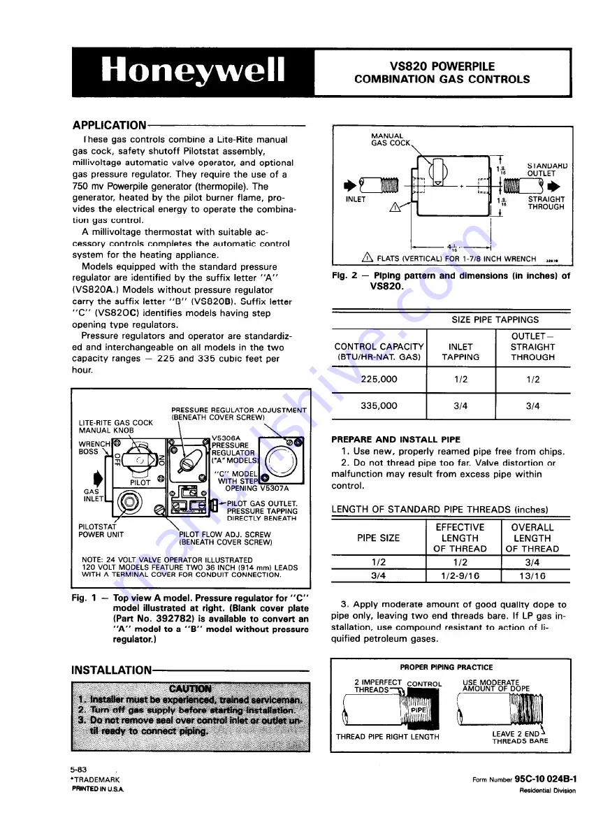
Страница 1: ...NG DIRECTLY BENEATH PlLOTSTAi POWER UNIT PILOT FLOW ADJ SCREW BENEATH COVER SCREW NOTE 24 VOLT VALVE OPERATOR ILLUSTRATED 120 VOLT MODELS FEATURE TWO 36 INCH 914 mm LEADS WITH A TERMINAL COVER FOR CONDUIT CONNECTION MANUAL GAS COCK STANDARD OUTLET I INLET STRAIGHT THROUGH 4 W A FLATS VERTICAL FOR l 7 8 INCH WRENCH a Fig 2 Piping pattern and dimensions in inches of VS820 SIZE PIPE TAPPINGS 225 000 ...

Страница 2: ...millivoltage controls to line voltage or to a transformer Since the entire system is powered by the millivoltage generated by the Powerpile generator it is important to clean and scrape all wires before connecting Solder and tape all necessary splices using rosin flux to prevent corrosion Tighten terminal screws Total con trol circuit wiring must not exceed 30 feet of 2 wire 18 gauge cable or 50 f...

Страница 3: ...ing checked Other appliances must remain off and the pilot extinguished or their consumption deducted from the meter reading A MODEL PROCEDURE with pressure regulator 1 Check input to main burner by clocking gas meter or by using a pressure gauge manometer connected to downstream tapping Fig 1 The standard natural gas model is factory set at 3 5 inches WC outlet pressure and the standard LP gas mo...

Страница 4: ...for pilot tubing connection 386449 Pilot gas filter 391158 OPERATING INSTRUCTIONS FOR THE HOMEOWNER MPORTANT Follow the operating instructions provided by the manufacturer of your heating appliance The infor mation below will be of assistance in a typical con trol application but the specific controls used and the procedures outlined by the manufacturer of your appliance may differ requiring speci...

Отзывы: