V4730C/V8730C/V4734C 1:1 Gas/Air Servo Regulated Gas Valves
EN2R-9074 0612R1-NE
11
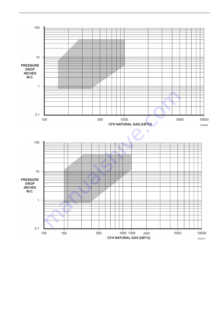
Fig. 11: Capacity curves for V4730C/V8730C and VMU 300 Venturi, 1 in. size.
Fig. 12: Capacity curves for V4730C/V8730C and VMU 335 Venturi, 1-1/4 in. size.
Страница 1: ...Unit VMU and dc fan are used for modulating premix appliances such as gas bur ners gas boilers rooftop units makeup air units and process ap plications FEATURES Wide modulation range 14 to 100 of burner load 24 Vac and 120 Vac models Main valve body with two shutoff seats double block valve Closing time less than one second Mesh screen strainer between inlet flange and main body Various pressure t...
Страница 2: ...4 mBar Note CSA Certification to 1 2 psi Connections 1 8 in 3 mm NPT pressure taps at inlet and outlet flanges Eight flange connections are provided at the main body to mount either a pressure switch high or low or a ValveProving System VPS Torsion and Bending Stress Pipe connections meet EN151 Group 2 requirements Electrical Equipment Standard DIN plug connector with 36 in 914 mm leadwires Valve ...
Страница 3: ...wall 3 cu in hr 50 cm3 h at test pressure of 0 87 psi 6 mBar and 7 83 psi 540 mBar First Valve 2 5 cu in hr 40 cm3 h at test pressure of 0 87 psi 6 mBar and 7 83 psi 540 mBar Second Valve 2 4 cu in hr 40 cm3 h at test pressure of 0 87 psi 6 mBar and 7 83 psi 540 mBar High Pressure Test In the OFF condition the valve will withstand 21 75 psi 1 5 Bar inlet pressure without damage Accessories FL02000...
Страница 4: ...734C 1 1 Gas Air Servo Regulated Gas Valves 4 EN2R 9074 0612R1 NE Fig 1 V4730C V8730C Gas Valves 1 2 in 13 mm and 3 4 in 19 mm size dimensions in in mm Fig 2 V4730C V8730C Gas Valves 1 in 25 mm size dimensions in in mm ...
Страница 5: ... V8730C V4734C 1 1 Gas Air Servo Regulated Gas Valves EN2R 9074 0612R1 NE 5 Fig 3 V4730C V8730C Gas Valves 1 1 4 in 32mm size dimensions in in mm Fig 4 V4734C Gas Valves 1 1 4 in 32mm size dimensions in in mm ...
Страница 6: ...R1 NE Fig 5 Venturi 150 335 kW with 1 2 in to 1 in gas valves and valve shutoff kit installed dimensions in in mm See Table 3 for dimensions Table 3 Dimensions in inches millimeters Valve Size in inches A B C D 1 2 3 4 6 1 4 159 15 15 16 405 2 15 16 75 7 7 1 2 191 1 8 5 16 211 ...
Страница 7: ...V4730C V8730C V4734C 1 1 Gas Air Servo Regulated Gas Valves EN2R 9074 0612R1 NE 7 Fig 6 Venturi 500kW with V4730 gas vlave and valve shutoff kit installed dimensions in in mm part 1 ...
Страница 8: ...V4730C V8730C V4734C 1 1 Gas Air Servo Regulated Gas Valves 8 EN2R 9074 0612R1 NE Fig 7 Venturi 500 kW with V4730 gas valve and valve shutoff kit installed dimensions in in mm part 2 ...
Страница 9: ...V4730C V8730C V4734C 1 1 Gas Air Servo Regulated Gas Valves EN2R 9074 0612R1 NE 9 Fig 8 V4734 VMU 500 680 ...
Страница 10: ... V4734C 1 1 Gas Air Servo Regulated Gas Valves 10 EN2R 9074 0612R1 NE Fig 9 Capacity curves for V4730C V8730C and VMU 150 Venturi 1 2 in size Fig 10 Capacity curves for V4730C V8730C and VMU 300 Venturi 3 4 in size ...
Страница 11: ... V4734C 1 1 Gas Air Servo Regulated Gas Valves EN2R 9074 0612R1 NE 11 Fig 11 Capacity curves for V4730C V8730C and VMU 300 Venturi 1 in size Fig 12 Capacity curves for V4730C V8730C and VMU 335 Venturi 1 1 4 in size ...
Страница 12: ...4734C 1 1 Gas Air Servo Regulated Gas Valves 12 EN2R 9074 0612R1 NE Fig 14 Capacity curves for V4734C V8734C and VMU 680 Venturi 1 1 4 in size Fig 13 Capacity curves for V4730C V8730C and VMU 500 Venturi 1 1 4 in size ...
Страница 13: ... commissioning the burner check for proper lightoff and verify correct fuel air mix and combustion quality through out the entire firing range from lowest to highest fan speeds used Mounting Locations The distance between the gas valve and the wall ground must be a minimum of 11 5 16 in 30 cm Fig 15 Regulating adjusting screw Main Gas Connection 1 Take care that dirt does not enter the gas valve d...
Страница 14: ...ure at first SSOV flange tap 2 inlet pressure at first SSOV P outlet pressure at first SSOV 3 inlet pressure at second SSOV 4 outlet pressure at second SSOV flange tap The following pressures can be measured 1 Inlet pressure tap on inlet flange 1 2 Pressure after inlet screen 2 3 Unregulated intermediate pressure pressure between the two shutoff seats P 4 Regulated intermediate pressure pressure b...
Страница 15: ...e rate of bubbles coming through the water stabili zes count the number of bubbles appearing during a ten se cond period Each bubble appearing represents a flow rate of 0 001 cfh 28 cch See Table 4 10 Close the upstream manual gas cock A 11 Remove the leak test tap from the valve body 12 Using a small amount of pipe sealant on the 1 8 in 3 mm NPT plug reinstall the plug in pressure tap point P 13 ...
Страница 16: ...a short in the electrical circuit and repair it as ne cessary WARNING Electrical Shock Hazard Can cause severe inju ry death or property damage Use extreme caution when troubleshooting line volta ge is present IMPORTANT Do not replace the valve until all other sources of trouble are eliminated SERVICE INFORMATION Scheduled Inspection and Maintenance Set up and follow a schedule for periodic inspec...