(22.9)
VALVE STEM TRAVEL (OPENING) IN INCHES [mm IN BRACKETS)
VALVE
TRAVEL (OPENING) IN INCHES [mm IN BRACKETS)
Страница 1: ...v5055 Honeywell Industrial Gas Valves 1 3 Inch Valves 4 Inch Valves Gas Flow vs0 Valve Opening ...
Страница 2: ...Table of Contents PAGE INTRODUCTION 1 VALVE CURVES 1 V5055A D 1 V5055B 5 V5055C E 9 CAPACITYCURVES 13 VALVE SlZlNG CHART 14 ...
Страница 3: ...tuators to provide proof of clo sure switch and valve seal overtravel interlock V5055D EValvesareforhighpressureapplications see Table 1 Seven valve sizes from 3 4 to 3 inches have NPT threaded connections Models are available with BSP PL threads V5055A B C Valves are available in a 4 inch size and have flange connections Most models have 1 4 inch upstream and down stream top and plug BSP PL threa...
Страница 4: ... Actuator V4055A Dc V4055B Ec V4062 V9055c Valve psi kPa psi kPa psi kPa psi kPa psi kPa psi kPa V5055A C 3 4 to 3 in 5 34 5 15 103 4 15 103 4 15 103 4 5 34 5 14 103 4 V5055A C 4 in 3 20 7 15 103 4 5 34 5 15 103 4 3 20 7 15 103 4 V4055B 3 4 to 3 in 5 34 5 15 103 4 15 103 4 15 103 4 5 34 5 15 103 4 V5055B 4 in 3 20 7 15 103 4 5 34 5 15 103 4 3 20 7 15 103 4 V5055D E 3 4 1 1 1 4 1 1 2 in 5 34 5 75 5...
Страница 5: ...m hr 3 4 665 18 8 1 960 27 2 1 1 4 1406 39 8 1 1 2 1717 48 6 2 3620 102 5 2 1 2 4250 120 3 3 5230 148 1 4 V5055A 10200 288 8 4 V5055B C 9180 259 9 a A joint venture of CGA Approvals Inc and AGA Labora tories Fig 1 Flow curves for V5055 Valves M9542 100 2 8 1 1 2 3 4 5 6 7 8 9 1 2 3 4 5 6 7 8 9 1 2 3 4 5 6 7 8 9 1 9 8 7 6 5 4 3 2 1 9 8 7 6 5 4 3 2 1 1 0 0 25 10 0 2 5 100 0 25 9 8 7 6 5 4 3 2 1 100 ...
Страница 6: ... 1 1 4 1 1 2 136308AA 2 2 1 2 3 136307AA Fig 2 Approximate dimensions of the 3 4 through 3 in V5055 Valves with valve actuator in in mm B E F C D A 1 1 4 INCH NPT DOWNSTREAM TAP AND PLUG 1 4 INCH NPT UPSTREAM TAP AND PLUG 1 32 5 KNOCKOUT FOR1 2 INCH CONDUIT 4 OCTAGON 1 9 32 27 32 21 4 3 23 32 5 127 94 5 6 3 4 171 5 ALLOW 2 IN 51 mm CLEARANCE FOR ACTUATOR REMOVAL M9585 3 4 1 1 1 4 1 1 2 2 2 1 2 3 V...
Страница 7: ...8 B1184 B1192 B1200 and B1218 GAS VALVE SIZING 1 Check the burner nameplate for a the type of gas used and b the gas flow capacity The capacity will be listedinBtu h Btusperhour orincf h cubicfootperhour 2 Call the gas utility for information on a the specific gravity sp gr and b Btu per cubic foot Btu cu ft for type of gas used 3 Find the capacity in cf h If the capacity is listed in Btu h conver...
Страница 8: ...water from entering the V4055 valve stem and spring chamber through the actuator Under certain condi tions some water may be retained by the external upper portion of the valve body The retained water is effectively excluded from the valve stem and spring chamber by a functional seal that is incorporated into the NEMA 4 rated actuator WHEN INSTALLING THIS PRODUCT 1 Read these instructions carefull...
Страница 9: ...TED INCORRECT WRENCH HERE STRAINS VALVE BODY M9580 3 Removetheprotectivecapsfromtheendsofthevalve Do not attach the valve actuator until the valve body instal lation is complete 4 Apply good quality pipe dope resistant to action of LP gas putting a moderate amount on the male threads only Use dope sparingly if pipe dope lodges on the valve seat it will prevent proper closure 5 Install valve with t...
Страница 10: ... not allow fuel to accumulate in the combustion chamber Iffuelisallowedtoenterthechamberfor longer than a few seconds without igniting an explosive mixture could result CAUTION 1 Do not put the system into service until you have satisfactorily completed the following Valve Leak Test all applicable tests described in the Checkout section of the Instructions for the flame safeguard control and any o...
Страница 11: ...ameter Seal off diameter is not to be confused with pipe size NOTE For international leak test requirements contact the office of the appropriate approval agency AFTER THE TEST 11 Close the upstream manual gas cock A 12 Close the test petcock F remove the test apparatus and replace the leak test tap plug D 13 Open the upstream manual gas cock A and energize the safety shutoff valve C 14 Testwithso...
Страница 12: ...ons of valve and bonnet seals in 3 4 through 3 in valves Failure to properly position and seat the seals in the valve body may result in a hazardous gas leak After the new bonnet assembly is installed or the bonnet is removed for any reason check for gas leakage around the bonnet seal Turn on the gas at the manual valve Paint the seal area with a rich soap and water solution Bubbles indicate a gas...
Страница 13: ...11 60 2307 10 ...
Страница 14: ...rol Home and Building Control Helping You Control Your World Honeywell Inc Honeywell Limited Honeywell Limitée 1985 Douglas Drive North 740 Ellesmere Road Golden Valley MN 55422 Scarborough Ontario M1P 2V9 Printed in U S A QUALITY IS KEY ...
Страница 15: ...guide for use with LOW HIGH or MODULATING actuators or with ON OFF actuators to aid in smooth light off The V5055C Gas Valve is designed for ON OFF service When used with the proper actuator it meets Factory Mutual requirements for valve closed indication and Underwriters Laboratories Inc requirements for valve seal overtravel interlock The V5055D Gas Valve is designed for ON OFF service in high p...
Страница 16: ... V5055A D 1 INCH NPT I I A 3 2 1 a VALVE STEM TRAVEL OPENING IN INCHES mm IN BRACKETS w 31 80 70 V5055A D l 1 4 INCHES NPT loo 4 90 Bo 70 VALVE STEM TRAVEL OPENING IN INCHES mm IN BRACKETS1 23m 2 ...
Страница 17: ...V5055A D l 1 2 INCHES NPT lO 2 5 G VALVE STEM TRAVEL OPENING IN INCHES mm IN BRACKETS I V5055A D 2 INCHES NPT I 1 lO 0 2S m VALVE SiEM TRAVEL OPENING IN INCHES mm IN BRACKETS Z4pI 3 7043311 ...
Страница 18: ...WI low 1281 2 51 IS 11 7 6 10 2 12 7 j15 61 j17 81 2 0 3 1 22 91 25 4 27_i VALVE STEM TRAVEL OPENING IN INCHES mm IN BRACKETS ma V5055A D 3 INCHES NPT lO zcl 30 2 5 5 1 7 61 VALVE STEM TRAVEL OPENING IN INCHES mm IN BRACKETS szfi 4 ...
Страница 19: ...I I L I I I 1 n 10 20 30 A0 s 0 60 76 60 96 _ _ 1 2 5 1 Iii 1 7 61 10 2 12 7 IS 61 17 8 120 31 I2291 VALVE SfEM TRAVEL OPENING IN INCHES mm IN BRACKETS1 NIB V5055B 3 4 INCH NPT 0 lO 25 loo 80 30 70 60 E s LL 50 40 L 30 20 10 0 VALVE STEM TRAVEL OPENING IN INCHES mm IN BRACKFIS1 1214 5 70 8311 ...
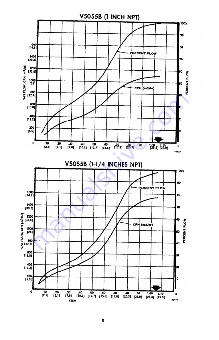
Страница 20: ...117 91 20 3 22 9 25 41 27 9 VALVE STEM TRAVEL OPENING IN INCHES mm IN BRACKETS 2 a VALVE StEM TRAVEL OPENING IN INCHES mm IN BRACKETS I_ 6 ...
Страница 21: ...lloo 1281 g 2800 11 211 I l r I 2001 I I I I S 61 VALVE STEM TRAVEL OPENING IN INCHES mm IN BRACKETS 7 31B V5055B 2 INCHES NPT 251 5 11 7 6 10 21 1 2 7 1 15 61 17 8 I20 31 122 91 125 41 t27 91 VALVE STEM TRAVEL OPENING IN INCHES mm IN BRACKETS was4 ...
Страница 22: ...V5055B 2 l 2 INCHES NPT 2wo WI 168 I12 3ou WI PI lO I2 51 VALVE STEM TRAVEL OPENING IN INCHES mm IN BRACKETS 7 3SA V5055B 3 INCHES NPT lO 25 VALVE STEM TRAVEL OPENING IN INCHES mm IN BRACKETS Z3U 8 ...
Страница 23: ...V5055B 4 INCHES FLANGED I I I 1 d I m zo IO D VALVE STEM TRAVEL OPENING IN INCHES mm IN BRACKETS 42 W V5055C E 3 4 INCH NPT VALVE STEM TRAVEL OPENING IN INCHES mm IN BRACKETS U2S 70 8311 ...
Страница 24: ...V5055C E 1 INCH NPT VALVE STEM TRAVEL OPENING IN INCHES mm IN BRACKETS 423 8 V5055C E l 1 4 INCHES NPT 1 0 lO 2 5 I i 2 I l E i 2 1 6 _ 0 VALVE STEM TRAVEL OPENING IN INCHES mm IN BRACKETS U Z S 10 ...
Страница 25: ... l 1 2 INCHES NPT 2ooo WI 10096 90 50 70 60 L 3 LL 60s 40 30 20 10 0 VALVE STEM TRAVEL OPENING IN INCHES mm IN BRACKETS ZllB V5055C E 2 INCHES NPT VALVE STEM TRAVEL OPENING IN INCHES mm IN BRACKETS A 11 704311 ...
Страница 26: ...I 2ou WI WI 1 VALVE STEM TRAVEL OPENING IN INCHES mm IN BRACKETS1 u u V505SC E 3 INCHES NPTI lO 2 5 i ii I S i 8 2 1 9 I k VALVE STEM TRAVEL OPENING IN INCHES mm IN BRACKETS 47 1sA 60 m 50 L 2 La 505 0 z 4o 3 0 2 0 1 0 0 12 ...
Страница 27: ...V5055C 4 INCHES FLANGED D t I I 4 1 d I VALVE STEM TRAVEL OPENING IN INCHES mm IN BRACKETS ZLB Capacity Vs Pressure Drop for all V5055 Valves ...
Страница 28: ...ure Drop across valve valve open a psi apressure drop must not exceed l 2 the inlet pressure in wc in wc in wc I V a l v e S i z einches 13 91 2 j Ordering Specification No V5055 I INSTRUCT1 ONS NOTE If natural gas specific gravity 0 64 is used 3 Draw line 3 0 from Outlet Pressure to skip steps one and two and start with step three 1 Draw line 0 Pressure Drop Convert pressure from inch WC to 1 fro...
Страница 29: ...adaptabletocommer cial and industrial installations that require close control of large gas capacities Variety of valve sizes firing rate motors and link ages For most modulating applications that do not require final shutoff service of firing rate valve Ruggedcastaluminumbodyprovidesdurabilityand maintenance free operation Compatible with Modutrol Motor and Q100A or B Linkage Actionator Motor and...
Страница 30: ... MH5968 Vol I Section 1 Guide No MHKZ Fig 1 V51E Valves Flow Capacities Ordering Information When purchasing replacement and modernization products from your TRADELINE wholesaler or your distributor refer to the TRADELINE catalog or price sheets for complete ordering number or specify 1 Valve model 2 Valve size 1 1 2 2 2 1 2 3 4 inches 3 Accessories 4 Order motor and linkage separately Refer to ap...
Страница 31: ... 5 21 64 67 5 80 2 97 6 102 4 135 3 A A 1 in mm 1 9 16 1 13 16 2 5 16 2 25 64 3 5 32 39 7 46 0 58 7 60 7 80 2 B B in mm 4 1 4 4 1 4 4 13 16 5 5 3 8 108 0 108 0 122 2 127 0 136 5 C C in mm 3 1 32 3 17 32 4 23 32 4 23 32 5 17 64 77 0 89 7 119 9 119 9 133 8 D D in mm M9532 1 2 1 1 MAXIMUM DIMENSIONS NOMINAL DIMENSIONS 2 V51E DIMENSIONS ...
Страница 32: ... 7 8 9 1 2 3 4 5 6 7 8 9 1 2 3 4 5 6 7 8 9 1 90 80 70 60 50 40 30 20 10 9 8 7 6 5 4 3 2 1 0 9 0 8 0 7 0 6 0 5 0 4 0 3 0 2 0 1 1000 10000 100000 CAPACITY IN cf h WITH 0 64 SP GR GAS 1 cf h 0 0283 m3 hr PRESSURE DROP INCHES WC 1 in wc 0 25 kPa 2 in 3 in 4 in 1 in 1 2 MAXIMUM OPENING ANGLE 30 40 50 30 50 45 57 55 45 35 45 40 50 60 40 50 60 55 45 55 V51E SPECIFICATIONS ...
Страница 33: ...Q100A LINKAGE ON V51E FIG 4 Any special parts nuts or screws needed are furnished in bag assemblies Install the motor and linkages as follows 1 Mount plate on stop bracket with three No 10 screws and lock washers 2 Mount motor on plate with four 1 4 in screws lock washers and nuts 3 Remove motor crank arm assembly from motor and discard it 4 Install the special crankarm in position shown With cran...
Страница 34: ...9533 COVER END CLAMP SCREW DRIVE PIN CRANK ARM LINK MOUNTING PLATE STOP BRACKET OPERATING LEVER LOCATED BEHIND STRAIN RELEASE STRAIN RELEASE SPRING ACTUATING ARM LINKAGE PIN V51 VALVE INSTALLING ACTIONATOR MOTOR AND Q100C LINKAGE ON V51E FIG 6 1 Mount plate on stop bracket with three No 10 screws and lock washers 2 Mount motor on plate with 4 1 4 in 108 0 mm hex head screws and lock washers 3 Inst...
Страница 35: ...ket holes 3 Insert the flat head screws supplied with the linkage assembly through plate spacers and stop bracket and into each hex Tighten securely The spacers prevent contact of adapter plate and stop bracket See Fig 9 4 Mount the lever arm 13 3 4 in 349 3 mm supplied with the motor so the load takeoff holes will be at the same end of the valve as the valve actuating arm NOTE Both motor lever an...
Страница 36: ...osition ACTIONATOR MOTOR WITH Q100C LINKAGE AND V51E FIG 6 Minimum Flow Adjustments Usingthemotor drivevalvetotheopenposition Loosen the lock nut on the stop screw Turn this screw in against the operating lever until the desired maximum flow adjustment is obtained If fully open is the maximum position desired backoutthescrewuntilitsthreadedendisflushwiththestop bracket Tighten lock nut Maximum Flo...
Страница 37: ...e new properly reamed pipe free from chips 2 Do not thread pipe too far into pipe adapter Valve distortion or malfunction can result from excess pipe in the valve 3 Do not attach valve actuator until valve body installation is complete 4 Make sure O ring sealing surfaces are clean 5 Apply moderate amount of good quality pipe dope resistant to the action of liquid propane LP gas only on the pipe th...
Страница 38: ...washers as shown in Fig 4 4 Using the grease packet provided or equivalent general purpose lithium grease grease the O ring of the second valve Make sure the grease is applied evenly around the entire O ring 5 Insert the O ring into the greased O ring groove 6 Assemble the NOVV adapter to the second valve using the three bolts nuts and lock washers as shown in Fig 4 NOTE Use the three smaller bolt...
Страница 39: ... to the valve train 2 Apply a parallel jaw wrench only to the pipe adapter flat next to the pipe being inserted Fig 7 A wrench applied to the valve body itself or to the end farthest from the pipe being inserted can distort the casting causing a malfunction Do not use the valve as a lever 3 Make sure the gas flow is in the same direction as the arrow on the valve body 4 Paint the pipe adapters and...
Страница 40: ...neywell Limited Honeywell Limitée 155 Gordon Baker Road North York Ontario M2H 3N7 Home and Building Control Honeywell Inc Honeywell Plaza P O Box 524 Minneapolis MN 55408 0524 Printed in U S A on recycled paper containing at least 10 post consumer paper fibers www honeywell com ...