T7770A,B,C,D,E,F,G WALL MODULES
95-7538—4
2
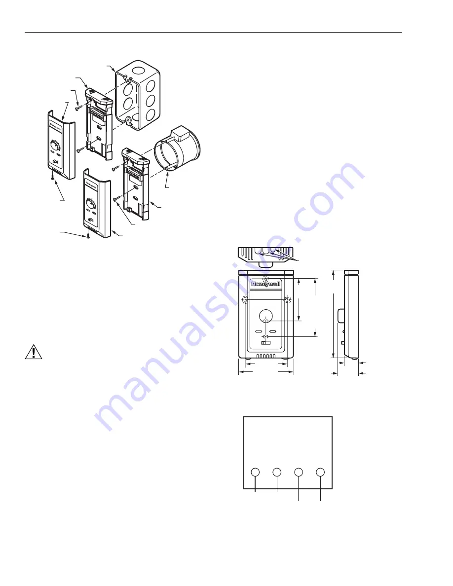
Fig. 3. Mounting wall modules on standard utility
conduit box or 60 mm wall outlet box.
See Fig. 4 for subbase mounting dimensions.
Wiring
Attach the wires from the device sensor terminals to the
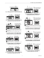
appropriate wall module terminals. See Fig. 5 through 16.
NOTE: None of these wall modules are compatible with
W7751A,C,E,G Controllers.
CAUTION
Improper Electrical Contact Hazard.
Screw type terminal blocks are designed to accept
no more than one 14 AWG (2.5 sq mm) conductor.
Connect multiple wires that are 14 AWG (2.5 sq mm)
with a wire nut. Include a pigtail with this wire group
and attach the pigtail to the individual terminal block.
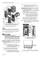
Wiring Modules Without a Removable Terminal Block
Attach the wires as follows:
1.
Connect controller sensor leads to the sensor screw
terminals.
NOTE: T7770A1006 have a 20K ohm sensor,
T7770A3002 have a 10K ohm sensor. They
are for use in averaging for the T7350. They do
not have E-bus network terminals.
2.
If the module has E-bus terminals, connect the
controller E-bus leads to these screw terminals.
NOTE: Wire the E-Bus using Level IV 22 AWG
(0.34 sq mm) plenum or non-plenum rated,
unshielded, twisted pair, solid conductor wire.
NOTE: Unless otherwise noted, sensor and E-Bus
terminals are not polarized; reversing the two sensor
leads does not affect the signal.
Wiring Modules With a Removable Terminal Block
Wire the terminal blocks as follows:
1.
For single wires, strip 3/16 in. (5 mm); for multiple wires
going into one terminal, strip 1/2 in. (13 mm) insulation
from the conductor.
2.
If two or more wires are being inserted into one
terminal, twist the wires together before inserting.
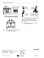
NOTE: When two or more wires are being inserted
into one terminal, be sure to twist them
together. Deviation from this rule can result
in improper electrical contact. See Fig. 17.
3.
Insert the wire in the required terminal location and
tighten the screw to complete the termination.
4.
Verify wall module wiring with Fig. 5 through 16.
NOTE: Wire the E-Bus using Level IV 22 AWG (0.34 sq mm)
plenum or non-plenum rated, unshielded, twisted
pair, solid conductor wire.
Fig. 4. T7770A,B,C,D,E,F,G Subbase
dimensions in in. (mm).
Fig. 5. Wiring diagram for T7770A20XX Wall Modules.
M17989
STANDARD UTILITY
CONDUIT BOX
SUBBASE
NO. 6 SCREW
60 mm WALL
OUTLET BOX
SUBBASE
3.5 mm SCREW
FRONT COVER
BUTTON
HEAD
SOCKET
CAP SCREW
BUTTON
HEAD
SOCKET
CAP SCREW
70
65
60
55
75
auto
0 1
80
85
FRONT COVER
70
65
60
55
75
auto
0 1
80
85
15/16
(23)
M17990
3-3/16 (80)
1-1/4 (32)
5-1/16
(128)
KNOCKOUTS FOR
EUROPEAN APPLICATIONS
2-3/8 (60)
2-3/8
(60)
STANDARD
UTILITY
CONDUIT
BOX (2 X 4)
MOUNTING
HOLES
SENSOR SENSOR E-BUS
E-BUS
SENSOR
SENSOR
NETWORK BUS
NETWORK BUS
M20359
E-BUS TERMINALS
ARE NOT USED FOR
C-BUS DEVICES.


