95C-10903-1
T451, T651 MOTOR-RATED PRECISION THERMOSTATS
SPECIFICATIONS • ORDER INFORMATION
ORDERING INFORMATION
When purchasing replacement and modernization products from your TRADELINE® wholesaler or your distributor, refer to the
TRADELINE catalog or price sheets for complete ordering number, or specify:
1. Model
2. Electrical load(s)
3. Accessories.
If you have additional questions, need further information, or would like to comment on our products or services, please write
or phone:
1. Your local Honeywell Home and Building Control Sales Office (check white pages or phone directory).
2. Home and Building Control Customer Satisfaction
Honeywell Inc., 1885 Douglas Drive North.
Minneapolis, MN 55422 (612) 951-1000
3. In Canada — Honeywell Limited, 35 Dynamic Drive, Toronto, ON M1V 4Z9, 1-800-405-9835.
International Sales and Service Offices in all principal cities of the world. Manufacturing in Australia, Canada, Finland, France,
Germany, Japan, Mexico, Netherlands, Spain, Taiwan, United Kingdom, U.S.A.
Important: The specifications given in this publication do
not include normal manufacturing tolerances. Therefore this
unit may not exactly match the listed specifications . This
product is tested and calibrated under closely controlled
conditions, and some minor differences in performance can
be expected if these conditions are changed.
Models:
T451A SPST and T451B DPST (with positive off) for
heating only.
T651A SPDT for heating/cooling.
Control Range:
44 - 86°F (7 - 28°C) for models T451A, T651A.
50 - 86°F (10 - 28°C) for model T451B.
Sensing Element: Vapor-filled dual diaphragm.
Differential: 2°F (1°C)
Droop: 2°F @ mid load range.
Barometer Sensitivity: 1/8°F/”wc (0.3°C/kPa).
Thermometer: 50 - 90°F (10 - 30°C) in 10°F (5°C) increments.
Electrical Ratings:
50/60Hz
120 V
208V
240V
277V
Full Load
9.8A
5.6A
4.9A
4.2A
Locked Rotor
58.8A
33.6A
29.4A
25.2A
Pilot Duty
125 VA
Resistive
22A Non Inductive 19ANI
Heating Only
2.5kW 4.5kW 5kW
Finish: Classic beige-and-light gold standard.
White models available.
Mounting:
Mounts directly on vertical, single-gang NEMA Standard
(2” x 4”) electrical box.
Wiring Connections:
6” (150 mm) leadwires suitable for connecting to aluminum
conductors wiring if used with approved special service
CO/ALR solderless wire connectors. Leadwires color-
coded red for heating, blue for cooling, black for common.
Approvals:
Canadian Standards Association Certified; File No. LR1322
Performance Certified for electric heating per C273.4A.
UL file E47434.
Accessories:
272804A Range stops and cover locking assembly
(included in selected models only).
220213 Wallplate, covers old T451/T651 (1000 series)
wall marks.
TG511 Thermostat guard for security and protection.
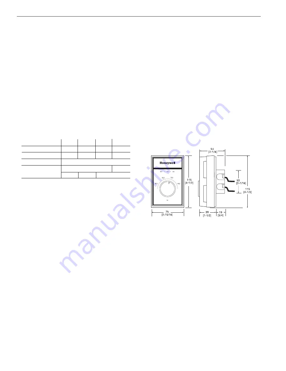
Fig. 1 — Dimensions of T451, T651 in inches (mm):
2


