background image

OPERATOR MANUAL // INDEX 

HONEYWELL 

20 

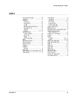
INDEX

Cleaning Products .................. 16 
Conduit.................................... 9 
Detector 

Cleaning ............................. 16 
Enclosure ........................... 10 
LEDs .................................... 6 
Maintenance Schedule ........ 16 
Replacement....................... 17 
Status .................................. 6 
Wiring ........................... 11,  18 

Detector Fault 

Input Voltage ...................... 16 
No Power ........................... 16 
Relay .................................. 16 
Self-Checking ..................... 16 

ESD ........................................ 9 
Explosion-Proof........................ 5 
False Alarms ............................ 6 
Field-of-View............................ 6 
FireBus .................................... 6 
FireBus 

Wiring .................................. 9 

FireLogic ................................. 6 
Flame Detector (See Detector) .. 6 
Grounding ................................ 9 

Installation ............................... 9 

Conduit ................................ 9 
Detector ............................. 11 
Enclosure ........................... 10 
Precautions .......................... 9 
Static Damage ...................... 9 

Layout Planning ....................... 9 
Maintenance .......................... 15 
Multi-Spectrum (See Detector) .. 6 
Optical Fire Detector      

(See Detector) ...................... 6 

Personnel - Qualified .............. 15 
Power...................................... 9 
Relay 

FAULT .......................... 13,  18 
FIRE ............................. 13,  18 

Removing Modules ................. 13 
SS2 (See Detector) .................. 6 
SS2-A ................................... 13 
SS2-AH ................................. 13 
SS2-AM ................................. 13 
SS2-AN ................................. 13 
Stand-Alone ............................. 5 
Static Damage ......................... 9 
Test Source ............................. 7 
Theory of Operation ................. 6 
Troubleshooting ..................... 15 

Содержание SS2 Series

Страница 1: ...Installation Guide and Operating Manual Multi Spectrum Digital Electro Optical Fire Detectors Models SS2 A SS2 AN SS2 AH and SS2 AM Stand Alone Mode ...

Страница 2: ...ptical Path Integrity CM1 CM1 A DartLogic FireLogic Fire Signature Analysis FireBusI FireBusII FirePic FirePicII FirePicIII FirePix FirePicture FSC Fire Sentry Corporation Fire Sentry Corp FSX All FSX Nomenclature Variations such as FS2 FS2X FS3 FS3X FS4 FS4X FS5 FS5X FS6 FS6X FS7 FS7X FS8 FS8X FS9 FS9X FS10X FS10X FS11 FS11X FS12 FS12X FS14 FS14X FS15 FS15X FS16 FS16X FS17 FS17X FS18 FS18X FS19 F...

Страница 3: ...f not avoided may result in equipment or work data on the system being damaged or lost or may result in the inability to properly operate the process CAUTION Indicates a potentially hazardous situation which if not avoided may result in minor or moderate injury It may also be used to alert against unsafe practices CAUTION Symbol on the equipment refers the user to the product manual for additional...

Страница 4: ...9 2 1 4 Power Supply Considerations 9 2 2 Enclosure Installation Optional 10 2 2 1 Swivel Mount SM2 10 2 2 2 Install Conduit If not already installed 10 Figure 2 Model SS2 Detector with SM2 Swivel Mount 10 2 3 Wiring Detectors 10 Figure 3 Model SS2 Detector Enclosure Side View 11 Figure 4 Model SS2 Detector Enclosure Back View 12 Figure 5 Models SS2 A SS2 AN SS2 AH and SS2 AM 12 SECTION 3 MAINTENA...

Страница 5: ...proved by California State Fire Marshal CSFM Factory Mutual FM Canadian Standards CSA CENELEC approval by FM Approvals Ltd Certification Service in compliance with the ATEX Directive Marking Class I Div 1 2 Groups A B C D Class II Div 1 2 Groups E F G Class III Class I Zone 1 AEx d IIC Ex d IIC Ex tb IIIC T135 C Read and understand this manual before installing or operating equipment ...

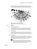
Страница 6: ...g UV and IR energy for munitions and air bag industries The Detector is housed in a Class I Div 1 Explosion Proof enclosure For more information refer to corresponding specification sheets There are operational advantages when the Detector is connected to an FS2000 Controller and FireBus The Detector also has flexibility to be re configured in the field It is simple to install and operate due to b...

Страница 7: ...e Detector status During Normal Operation both LEDs will blink every 10 seconds If a Model SS2 Detector has a Fault it de energizes the Fault relay and turns one 1 LED on The LED will not light if the Fault is a No Power Fault If the Fault condition such as a Low Voltage Fault is eliminated the Detector will automatically return to Normal Operation Faults caused by Excessive Input Voltage or tempe...

Страница 8: ...lens contamination has been identified 1 5 2 Automatic Testing The Model SS2 Detectors contain an internal source for self testing For testing the Model SS2 Detectors end to end for both optical path and window cleanliness use a Honeywell Analytics Model FT 2045 Test Lamp 1 5 3 Manual Testing For manual testing the Detector may be exposed to an actual industry standard open flame or to a Test Lamp...

Страница 9: ...5 Test Lamps are housed in an Explosion proof enclosure powered by internal rechargeable batteries and designed for indoor and outdoor use For additional information on the Test Lamp refer to Honeywell Analytics Specification SP0242 for the FT 2045 or 1505 008A for the FT 2145 ...

Страница 10: ...ved conduit trap or drain 3 For applications requiring a Class I Div 1 Explosion Proof rating install a seal within 6 inches of the enclosure 2 1 3 Wiring Recommendations Install a junction box near each Detector location Wire each Detector to the junction box Use screw down terminal strips inside the junction box to make the connections to the Detector s terminals and an Approved Fire Alarm Panel...

Страница 11: ... threaded insert should face the enclosure d Screw the enclosure bracket assembly onto the ball or swivel stud Turn the Detector until the stud bottoms against the enclosure Do not tighten While holding the enclosure tighten the jam nut against the bracket e While holding the enclosure loosen the socket head screw on the SM2 swivel mount Position the enclosure in such a way that the conduit openin...

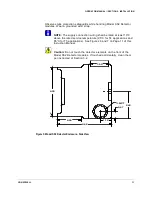
Страница 12: ...ted at least 10 C above the rated service temperature 95 C for T4 applications and 85 C for T5 applications See Figures 6 and 7 on Page 11 of this Insruction Manual Caution Do not touch the detector elements on the front of the Model SS2 Detector modules If touched accidentally clean them per instructed of Section 3 2 2 09 4 66 1 10 0 67 4 38 2 40 NPT 1 50 Figure 3 Model SS2 Detector Enclosure Sid...

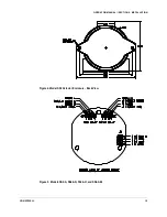
Страница 13: ...OPERATOR MANUAL SECTION 2 INSTALLATION HONEYWELL 12 Figure 4 Model SS2 Detector Enclosure Back View Figure 5 Models SS2 A SS2 AN SS2 AH and SS2 AM ...

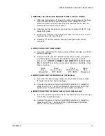
Страница 14: ...the J1 connector and firmly tighten down the two slotted screws with a small screwdriver DO NOT CONNECT ANY WIRES TO J1 Pin 2 or J1 Pin 3 Do NOT over tighten to prevent stripping or breaking See Figure 4 above Pin 1 Pin 2 Pin 3 Pin 4 Black Green or Blue White or Yellow Red Ground NOT USED NOT USED Power 3 WIRE THE DETECTOR FIRE RELAY All Models a Insert the Fire Alarm relay cables into the metal e...

Страница 15: ... module back over the three metal standoffs and screw it down with the three chrome plated screws into the standoffs b If necessary clean the detectors and windowed cover according to the instructions in Section 3 2 c Screw down the metal enclosure top windowed cover until secure and tighten the allen head tamper proof screw ...

Страница 16: ... a life threatening 120 or 240 Volts AC WARNING Hazardous voltages may be present during testing procedures Serious injury or death may result if personnel fail to observe safety precautions CAUTION Model SS2 Detector modules and their components are susceptible to permanent damage due to electrostatic discharge ESD DO NOT handle a module without adequate grounding precautions If Model SS2 Module ...

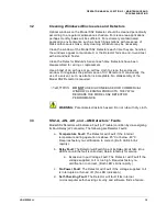
Страница 17: ...he Model SS2 Detector is required DO NOT USE SILICONE BASED OR COMMERCIAL WINDOW CLEANING PRODUCTS THEY WILL DEGRADE THE MODEL SS2 DETECTOR PERFORMANCE WARNING Potential electrostatic hazard Do not rub with dry cloth 3 3 SS2 A AN AH and AM Detectors Faults Model SS2 Detectors will indicate a Fault or Trouble condition by de energizing its Fault Relay J2 connector The following are Detector Faults ...

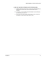
Страница 18: ...located on the bottom of the module Be sure to note the connection location of each wire 6 Install another module Reconnect the wires to the new module Make sure the module is correctly aligned Carefully re install back over the three metal standoffs Re install the three chrome plated screws Be careful not to touch the sensor elements If they are accidentally touched clean as instructed in Section...

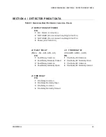
Страница 19: ...USED Do not connect anything to this Pin 4 Power 24 Volts D C J2 FAULT RELAY J2 FIRE RELAY 2 SS2 A AN AM AML AH SS2 AMD AMDL AHD PIN PIN 1 Fault Relay Common 1 Fire Relay 2 Common 2 Fault Relay Normally Closed 2 Fire Relay 2 Normally Open 3 Fault Relay Common 3 Fire Relay 2 Common 4 Fault Relay Normally Open 4 Fire Relay 2 Normally Closed J3 FIRE RELAY PIN 1 Fire Relay Common 2 Fire Relay Normally...

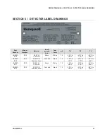
Страница 20: ...LB 6093 049 SS2 0 020 Al 1100 Hl4 Black White 75 40 C to 85 C 40 C to 75 C 40 C to 60 C LB 6093 050 SS2 0 020 316 Stainless Steel Polished Black 75 40 C to 85 C 40 C to 75 C 40 C to 60 C LB 6093 051 SS2 0 020 Al 1100 H14 Black White 75 40 C to 85 C 40 C to 75 C 40 C to 60 C LB 6093 052 SS2 0 020 316 Stainless Steel Polished Black 75 40 C to 85 C 40 C to 75 C 40 C to 60 C ...

Страница 21: ...f View 6 FireBus 6 FireBus Wiring 9 FireLogic 6 Flame Detector See Detector 6 Grounding 9 Installation 9 Conduit 9 Detector 11 Enclosure 10 Precautions 9 Static Damage 9 Layout Planning 9 Maintenance 15 Multi Spectrum See Detector 6 Optical Fire Detector See Detector 6 Personnel Qualified 15 Power 9 Relay FAULT 13 18 FIRE 13 18 Removing Modules 13 SS2 See Detector 6 SS2 A 13 SS2 AH 13 SS2 AM 13 SS...

Страница 22: ...e commercial loss lost profits or savings or other incidental special or consequential damages arising out of or in connection with the use or inability to use such product to the full extent such may be disclaimed by law THIS WARRANTY DOES NOT COVER 1 Defects or damage resulting from use of the Product s in other than its normal and customary manner 2 Defects or damage from misuse accident or neg...

Страница 23: ...ience Valley 1 43 Digital Ro 34 Gil Guro Gu Seoul 152 729 Korea Email analytics ap honeywell com Internet These Honeywell websites may be of interest to Industry Solution customers Honeywell Organization URL Corporate www honeywell com Honeywell Analytics www honeywellanalytics com Telephone Contact us by telephone at these numbers Organization Phone Number Americas Honeywell Analytics Inc 1 800 5...

Страница 24: ...1998M0908 Rev A July 2014 2014 Honeywell International Inc ...

Отзывы: