


SPYDER MODEL 7 VAV CONTROLLER INSTALLATION INSTRUCTIONS
27
31-00475-01
MODBUS RTU
The controller features a removable 2-wire with shield,
non-isolated, RS-485 interface suitable for Modbus
communication (terminal 16, 17, and 18). The terminal
block containing it is gray. The controller can function
only as a Modbus client. In general, the TIA/EIA 485
wiring rules must be followed.
The Spyder Model 7 VAV controller is conditionally
compliant with the “regular” Modbus device standard.
The controller differs from an unconditionally
compliant “regular” Modbus device standard in that it
does not support communication rates of 1.2, 2.4, and
4.8 kb/s (because these communication rates are not
market-relevant).
NOTE:
The recommended number of Modbus servers is
8, with a maximum of 155 read / write data points.
Modbus Considerations
The RS-485 interface suitable for Modbus
communication is 2-wire with shield non-isolated
hence the following considerations apply:
•
Maximum Modbus length (“L”): 4000 ft (9.6 –
78.8 kbps) or 2600 ft (115.2 kbps)
.
It is recom
-
mended that you select a low baud rate (for
example, 19.2 kbps) for reliable operation.
•
Use only shielded, twisted-pair of cables and
daisy chain topology.
•
Ground noise should not exceed the EIA-485
common mode voltage limit.
•
Must conform to TIA/EIA 485 cabling guidelines.
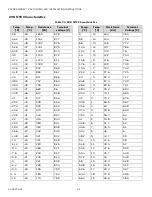
See
TIA/EIA 485 Cable Specifications on page 21.
•
It Should not extend beyond a single building.
Default Modbus values
Cables and Shielding
Use shielded twisted pair cable J-Y-(St)-Y 4 x 2 x 0.8 and
connect the Modbus shield to a noise-free earth ground
(only once per Modbus network).
Shielding is especially recommended when the Modbus
cable is installed in areas with expected or actual
electromagnetic noise. Avoiding such areas is to be
preferred.
You must use three wires:
•
One wire for
•
One wire for Modbus –
•
One wire for the signal common
When using one pair for Modbus (+) and Modbus (-) and
one wire of another pair for the signal common, CAT 5
cable may also be used.
Modbus RS-485 Repeaters
RS-485 repeaters are possible but have not been tested
by Honeywell; therefore, it is the installing or
commissioning person's responsibility to ensure proper
operation.
NOTE:
Each Modbus segment will require its own line
polarization and line termination (120
Ω
; the watt
-
age should be in the range of 0.25 – 0.5 W).
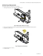
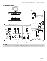
Wiring Topology
Only daisy chain wiring topology is allowed.
Fig. 32 Modbus Wiring Topology
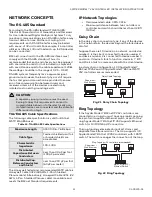
Other wiring topologies (such as star wiring and mixed
star wiring) are prohibited. This is to avoid
communication problems of the physical layer.
Fig. 33 Prohibited Wiring Topology (example)
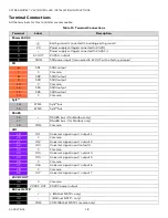
Table 21 Default Modbus Details
Specification
Description
Baudrate
76800
Parity
Even parity
Bytesize
8 bit
Stop bits
1 stop bit
SPYDER
MODEL 7
MODBUS
SERVER
MODBUS
SERVER
MODBUS
SERVER
MODBUS
SERVER
SPYDER
MODEL 7
MODBUS
SERVER
MODBUS
SERVER
MODBUS
SERVER
MODBUS
SERVER
MODBUS
SERVER
MODBUS
SERVER
X X