


SPYDER MODEL 7 VAV CONTROLLER INSTALLATION INSTRUCTIONS
21
31-00475-01
NETWORK CONCEPTS
The RS-485 Standard
According to the RS-485 standard (TIA/EIA 485:
“Electrical Characteristics of Generators and Receivers
for Use in Balanced Digital Multipoint Systems”), only
one driver communicating via an RS-485 interface may
transmit data at a time. Further, according to U.L.
requirements, each RS-485 interface may be loaded
with a max. of 32 unit loads. For example, if a controller
utilizes as little as 1/8 unit load each, up to 256 devices
can be connected.
BACnet connections to the RS-485 interfaces must
comply with the RS-485 standard. Thus, it is
recommended that each end of every bus be equipped
with a termination resistor (not included in shipment)
with a resistance equal to the cable impedance (120
Ω
;
the wattage should be in the range of 0.25 – 0.5 W).
RS-485 systems frequently lack a separate signal
ground wire. However, the laws of physics still require
that a solid ground connection be provided to ensure
error-free communication between drivers and
receivers unless all of the devices are electrically
isolated and no earth grounding exists.
CAUTION
CAUTION
A separate signal ground wire must be used.
Failing to obey this requirement can lead to
unpredictable behavior if other electrically non-
isolated devices are connected, and the potential
difference is too high.
TIA/EIA 485 Cable Specifications
The following cable specification is valid for BACnet
MSTP EIA 485 buses.
The Honeywell tested and recommended MSTP cable is
Honeywell Cable 3322 (18 AWG, 1-Pair, Shielded,
Plenum cable). Alternatively, Honeywell Cable 3251 (22
AWG, 1-Pair, Shielded, Plenum cable) is available and
meets the BACnet Standard requirements.
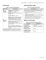
IP Network Topologies
•
Recommended cable: CAT5, CAT6.
•
Maximum distance between two controllers or
controller and switch should be less than 328 ft
(100 m).
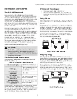
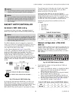
Daisy Chain
In the daisy chain connection type, if any of the devices
in the network fails, the devices beyond the failed device
also fail.
Suppose there are 10 devices in a network, and device
number 1 is the client, connected to device number 2,
and device number 2 is connected to device number 3,
and so on. If device 5 fails to function, device 6, 7, 8, 9,
and 10 also fails to communicate with the client device.
In a daisy chain configuration, 100 Spyder Model 7
BACnet IP VAV and 40 Spyder Model 7 BACnet MSTP
VAV controllers are recommended.
Fig. 21 Daisy Chain Topology
Ring Topology
If the Spyder Model 7 BACnet IP VAV controllers are
connected in a ring, you must have one rapid spanning
tree protocol supported Ethernet switch as part of the
ring. Spyder Model 7 BACnet IP VAV supports Ethernet
switch for 10/100 Mbps IP connection.
The ring topology eliminates broadcast storms and
duplicate frame transmissions. The loop supports 39
Spyder Model 7 BACnet IP VAV controllers with 1 RSTP
switch. The switch manages the connection of the loop.
Fig. 22 Ring Topology
Table 16. TIA/EIA 485 Cable Specifications
Maximum Length
4000 ft (9.6–76.8 kbps)
Cable Type
Twisted shielded pair (foil
or braided shields are
acceptable)
Characteristic
Impedance
100-130
Ω
Distributed
Capacitance Between
Conductors
Less than 30 pF per foot
(100 pF per meter)
Distributed Cap.
Between Conductors
and Shield
Less than 200 pF per foot
(60 pF per meter)
Daisy Chain Topology
#3
#2
#N
#1
#4
Supervisor/
Web Browser
Ring Topology (39 controllers recommended)
Supervisor /
Web Browser
#2
#3
Multi Port (RSTP)
Ethernet Switch
#1