Wiring Connections and Power Up
Make sure that the following power supply constraint is met.
1000
/
22
*
3
.
2
,
,
loop
Min
Txer
Min
S
R
V
V
V
Where
ohms
in
resistance
loop
is
ls
at termina
tage
supply vol
Minimum
r
Transmitte
is
tage
supply vol
minimum
is
,
,
loop
Min
Txer
Min
S
R
V
V
Wiring Options
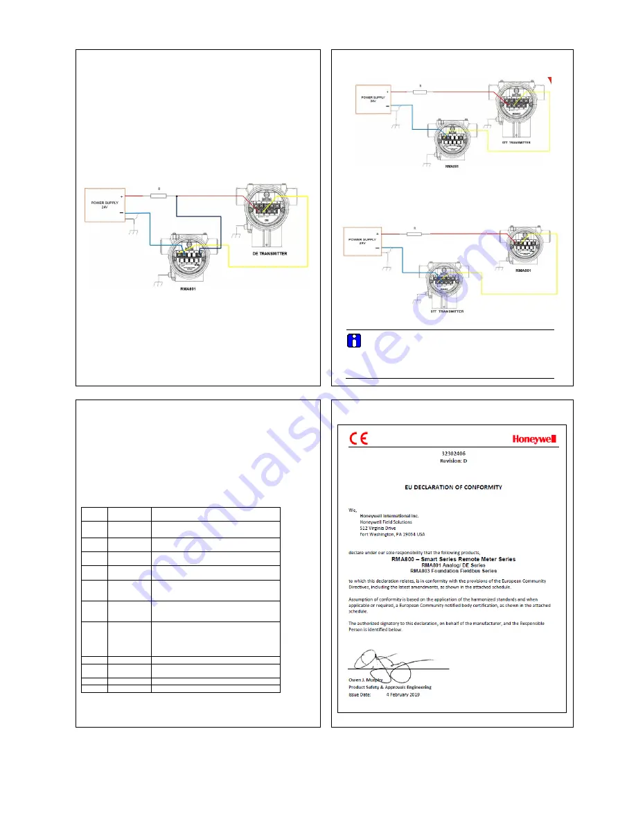
There are 3 wiring options for connecting Remote Indicator to the loop.
See
Figure 9,
Figure 9
and
Figure 8
for the wiring connections.
DE Devices
In this mode, the Remote Indicator shall be connected as shown in
Figure 8.
Figure 8: Remote Indicator connected to the negative loop wire
Once the wiring is complete, power on the loop. The RMA device will take 6s (approx.) to
turn on the display.
Note
– The resistor “R” indicates (shown for representation only) the loop resistor which is
needed for HART and DE communication and is typically provided by the user or control
system.
Analog (4-20mA) Devices:
Refer Figure 8 and 9 for the Remote Indicator Connection on the Negative and positive
side of the loop.
Figure 9: Remote Indicator connected to the negative loop wire
1.
Remote Indicator installed as explosion proof in Class I, Division 1, Group A
Hazardous (classified) locations in accordance with ANSI/NFPA 70, the US
National Electrical Code, with 1/2 inch conduit do not require an explosion-proof
seal for installation. If 3/4 inch conduit is used, a LISTED explosion proof seal must
be installed in the conduit, within 18 inches (457.2 mm) of the Remote Indicator.
Figure 10: Remote Indicator connected to the positive loop wire
ATTENTION
For all wiring options, ensure that RMA chassis ground terminal is
connected to earth ground.
Connect the Loop Power shield to earth ground at the power supply
end and not at RMA end. The shield shall be continuous from
transmitter through RMA till the power supply
:
DEVICE CONFIGURATION
Once the loop is powered, the RMA will be turned ON with a scrolling message “SmartLine”
appearing on the display.
For DE devices, the RMA is autoconfigured. For any DE configuration change in the
transmitter, database upload shall be performed to reflect the changes in RMA.
To configure the device, open the front cover of the device.
Use the ‘Menu’ and ‘Enter’ key buttons on display to configure the device. See table below
for configuration parameters.
Use the ‘Menu’ button to navigate the configuration parameters. Use the ‘Enter’ button to
select and set a parameter value.
1.
Temperature: °C, °F, °R, K, mV, Ohm
Pressure Engineering Units: inH2O@39ºF, mH2O@4ºC, cmH2O@4ºC, Torr,
mmH2O@68ºF, ftH2O@68ºF, inH2O@68ºF, inH2O@60ºF, atm, Pa, kPa, MPa, gf/cm2,
kgf/cm2, psi, mbar, bar, inHg@0ºC, mmHg@0ºC, mmH2O@4ºC.
SNO MENU
Parameters
Description
1
SEL PV
Select Process Variable (temperature,
pressure, loop out, % out)
2
UNIT
Select Engineering Unit
Units are visible as per PV selection
3
ENTLRV
Enter Lower Range Value
(Numeric Value)
4
ENTURV
Enter Upper Range Value
(Numeric Value)
5
CAL Lo
Input Calibration Low Point. See manual for
details of calibration
(Applicable in Analog Mode only)
6
CAL Hi
Input Calibration High Point. See manual for
details of calibration.
(Applicable in Analog Mode only)
7
B UNIT
Select Engineering Base Unit of Transmitter
Base Units visible as per PV selection
(Applicable in Analog Mode only)
8
CNTRST
Set LCD Contrast
9
RMA DG
RMA Diagnostic Messages. See manual for
details of diagnostic messages
10
FW VER
Firmware Version
EXIT
EXIT Menu
Appendix A. PRODUCT CERTIFICATIONS
A1 European Directive Information (CE Mark)


