background image

SEC-H-600 SECURITY CONTROLLER

95-7759—07

12

BOARD LAYOUT

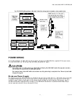
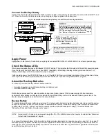
Figure 4 shows the location of LEDs, option slots, and other features of the SEC-H-600 Security Controller, with cover removed. 

For a side view of communications ports and other features, see Fig. 15 on page 26.

Fig. 4. Security Controller (SEC-H-600) board layout details.

About Screw Terminal Connectors

Screw-terminal connectors are shipped loose in a separate hardware bag. If desired, you can make wiring terminations to 

connectors 

before

 installing on the Security Controller circuit board pins. Please note the following:

• When you install a connector onto the board pins, terminal labels (on the circuit board) are 

covered

.

• Once installed, removal of larger connectors (readers, relay outputs) may be difficult, especially if wiring has been landed. 

Here, removal is recommended only if replacing the device.

In general, it may be easiest to wire to 

loose

 connectors (held next to pins), then install them after completing.

(one 4-position connector)

Option Slot 1 Area

Option Slot 

Connectors

NiMH battery 

pack Connector 

(see Fig. 15 on 

page 26)

Option Slot 2 Area

Earth Ground 

Connector 

Lug

Unsupervised Digital 

Inputs (1—3)

One 4-position connector

12Vdc SLA 

Backup Battery

Reader Input 2

(Wiegand 12V type)

Reader Input 1

(Wiegand 12V type)

LEDs for 

relay 

outputs

6 Pin End 

Connector 

(Expansion 

Modules)

Digital Supervised Inputs (1—6) 

Three 3-position connectors

Primary 

Ethernet 

(RJ-45) 

LAN1

Security 

Controller 

NiMH 

Backup 

Battery and 

Bracket

Mode Jumper 

(for serial shell 

access)

LAN1

STATUS

BEAT

LAN2

Status LEDs (visible with cover on)

6 Pin End 

Connector 

(Expansion 

Modules) 

includes

RS-485

Form-C Relay Outputs 1—4

Two 6-position connectors

RS-232

(DB-9)
COM1

each has one 

7-position 
connector

For External 

15Vdc Supply

USB Port
(top board)
Future Use

LEDs for COM1 
(RS-232) and 
COM2 (RS-485)

Содержание SEC-H-600

Страница 1: ...Documentation 5 SYSTEM PLANNING 5 Basic Design Rules SEC H 600 5 Estimating Power and Battery Requirements 6 Voltage Drop Considerations 7 Maximum Output Load Considerations 8 PREPARATION 8 Included in this Package 8 Material and Tools Required 9 PRECAUTIONS 9 Safety Precautions 9 Static Discharge Precautions 9 MOUNTING 10 Environmental Requirements 10 Physical Mounting 10 Removing and Replacing t...

Страница 2: ...r usage with readers 2 are general usage 3 digital inputs unsupervised for predefined system monitoring Additional security I O points are achieved by adding expansion modules A fully expanded SEC H 600 can support a total of 32 readers using 15 SEC H R2R expansion modules Or other combinations are possible with fewer readers but more general usage I O using SEC H RIO expansion modules See Expansi...

Страница 3: ...troller base board see Fig 4 on page 12 An option card typically provides additional communication ports NOTE Option cards not evaluated by U L Option card usage in a Security Controller is expected to be infrequent WARNING All power to the Security Controller must be OFF when installing or removing option cards or damage will occur Also you must be very careful to plug an option card into its con...

Страница 4: ...al SEC H R2R module SEC ENC H 2 Large Used for the Security Controller in larger job configurations it provides a DIN rail mount and an integral 30W 15Vdc power supply for the controller and a second DIN rail for expansion modules for example up to four 4 SEC H R2R modules The SEC H 600 controller plugs directly into the power supply see Fig 2 A supplied six conductor wiring harness not shown prov...

Страница 5: ...or more WEBs AX Security Enclosures with a model SEC ENC H 1 or SEC ENC H 2 used to house the SEC H 600 controller See WEBs AX Security Enclosure on page 4 4 All expansion modules must be connected to the Security Controller on an RS 485 communications trunk using a daisy chain topology Also each reader must be located within 500 feet of the reader input used For related details see Con nection Ov...

Страница 6: ...multiplier due to either charge level or age For example each SEC H RIO with all 8 relays energized draws about 0 4A 6 0W at 15Vdc When powered by the 12V backup battery Ah is calculated as follows 0 4A x 4 hours 1 60Ah x 1 25 2 0Ah To calculate the system total DC power supply requirements and minimum SLA backup battery capacity add up the total watts W and minimum Amp hours Ah for all devices Wh...

Страница 7: ...x 1 67Ah 2 x 2 0Ah 3 33Ah 6 68Ah 4 0Ah 14 01Ah Assuming that all equipment is located relatively nearby it could be housed in two large enclosures with each enclosure s 30W power supply providing ample 15Vdc power to equipment inside as follows SEC ENC H 2 A large SEC H 600 controller one SEC H RIO module two SEC H R2R modules 26W SEC ENC H 2 B large One SEC H RIO two SEC H R2R 16W Between Securit...

Страница 8: ...ation may need to have remote expansion modules mounted in unpowered Security Enclosures where they are powered locally using approved third party battery backed 12Vdc power supplies See the UL Requirements section Battery backed Power Supplies page 29 for a listing of approved power supply models Related wiring details are in the installation document for expansion modules see Related Documentati...

Страница 9: ...eral nature relating to the installation and start up of the Security Controller Be sure to heed these warnings to prevent personal injury or equipment damage WARNING The circuit powering the controller is from 120 to 240Vac at 50 60 Hz Disconnect power before installation or servicing to prevent electrical shock or equipment damage Make all connections in accordance with national and local electr...

Страница 10: ...t physically mounting the unit Before mounting the Security Controller install Option Cards if any in the unit See Removing and Replacing the Cover page 11 Refer also to the installation sheet that came with the option card Mount inside a WEBs AX Security Enclosure see previous Note onto the top 35mm wide DIN rail Plug the Security Controller directly into the integral power supply It it not neces...

Страница 11: ... unit and lift the cover off NOTE If expansion modules are plugged into the Security Controller you may need to slide them away from the unit to get to the cover tabs To replace the cover orient it so the cutout area for comm ports is correct then push inwards to snap in place Mounting on DIN Rail Removing from DIN Rail Security Controller Security Controller Tab holes align with tapped holes in e...

Страница 12: ...is recommended only if replacing the device In general it may be easiest to wire to loose connectors held next to pins then install them after completing one 4 position connector Option Slot 1 Area Option Slot Connectors NiMH battery pack Connector see Fig 15 on page 26 Option Slot 2 Area Earth Ground Connector Lug Unsupervised Digital Inputs 1 3 One 4 position connector 12Vdc SLA Backup Battery R...

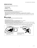
Страница 13: ...wer wiring Neatly label cables at both ends For example label should include Security Controller terminal s Device or Reader Neatly dress and tie or lace all wiring in a professional manner Gather together and tape all unused conductors in multiple conductor cables Ground all shield drain wires at the Security Controller enclosure using crimp ring terminals fastened to internal grounding studs scr...

Страница 14: ...below Keep this wire as short as possible Fig 6 Connect earth ground using supplied grounding wire to grounding lug In addition connect the earth grounding lug of each expansion module to earth ground in the same manner Cable Types and Lengths Recommended cable types and maximum lengths are as follows RS 485 communications between the Security Controller and expansion modules use a 24 AWG shielded...

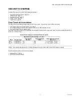
Страница 15: ...quest to exit One Relay Output for door strike control A default convention is used for the logical association between reader inputs supervised inputs and relay outputs for each door as shown in Table 4 below NOTE Terminal associations shown in Table 4 also apply if wiring a SEC H R2R 2 reader expansion module See the following sections below for more details Example Door 1 Wiring Other Terminal ...

Страница 16: ...or Door Terminal Associations the Security Controller has the following terminals Supervised Inputs 5 and 6 SI5 SI6 for general usage See Supervised Input page 18 Relay Outputs 3 and 4 for general usage See Auxiliary Relay Output Wiring page 21 Three unsupervised Digital Inputs DIs See Digital Input page 22 PS PS BT BT GND DC AX3 AX1 D1 AX2 D0 NC2 NO1 NC1 NO2 C1 C2 NC3 NO3 C3 NC4 NO4 C4 CARD READE...

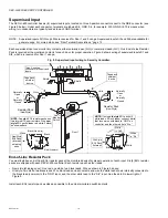
Страница 17: ...eld wires together and connect to the designated grounding point at the enclosure SeeFig 5 on page 13 Place the appropriate wires in the appropriate screw terminals of the 7 position reader connector Refer to the pinouts in Table 5 above for reader input designations Figure 8 above lists typical wiring colors Table 5 Pinouts for Card Reader Inputs Terminal Terminal Name Terminal Notes Typical cabl...

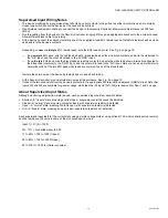
Страница 18: ...0 controller Each resistor pack has four leads New style shipping soon One red one white two black leads Wire as shown in Figure 9 above Old style Two white two black leads Wire black leads across contacts and wire the white lead shown internally connected to the black lead common to the GND input and the other white lead to the SIn input See the detail in lower right of Figure 9 Install each EOL ...

Страница 19: ... input and the other white lead to the SIn input Note you can use a multimeter to determine which of the two EOL pack white leads are common to one of the black leads Insulate the shield wire at the device by taping back or using shrink tubing At the Security Controller ground shield drain wires at the enclosure See Fig 5 on page 13 Connect the two conductors from the device s contacts to the appr...

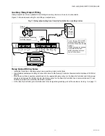
Страница 20: ...icator for each relay output is located next to that output s C common terminal on the circuit board when lit that relay is energized Therefore a circuit wired through the normally open NOn terminal is On closed when the LED is lit and Off open when the LED is not lit Door Strike Wiring Typical fail secure door strike wiring in this case for Door 1 using relay output 1 is shown in Figure 10 below ...

Страница 21: ...ary output device to the appropriate relay output on the Security Controller and to the power supply used to power the strike or device Each relay output on the Security Controller has a common terminal C and normally open NO and normally closed NC terminal At the Security Controller ground shield wires to the designated grounding point at the enclosure See Fig 5 on page 13 GND DC AX3 AX1 D1 AX2 D...

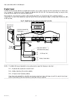
Страница 22: ... H 600 controller Fig 12 Digital input wiring example to Security Controller NOTE The WEBs AX Security Application is pre configured to support the following connections DI1 Tamper switch typically for enclosure door DI2 Battery status bad if contacts available DI3 AC power fail if contacts available Depending on the installation not all DIs may require connection In almost all cases input DI1 is ...

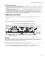
Страница 23: ...ecurity Controller using ports on the bottom of the unit Fig 4 which include Ethernet Serial NOTE Prior to connecting cables provide strain relief for them to prevent damage to the controller Fig 13 Security Controller SEC H 600 bottom side cover removed Ethernet Two female 10 100 Mbit Ethernet connections are provided on the Security Controller These are RJ 45 connectors labeled LAN2 and LAN1 Use...

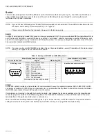
Страница 24: ... the mode jumper see Fig 4 on page 12 in the Serial Shell position RS 485 An RS 485 optically isolated port is dedicated for communications to security expansion modules SEC H R2R SEC H RIO and always operates as COM2 Wiring is not necessary to any modules that directly attach in line with the Security Controller the RS 485 signal passes through the 6 position end connectors If modules are not mou...

Страница 25: ...N H in a WEBs AX Security Enclosure SEC ENC H 1 or SEC ENC H 2 provides 30W of regulated 15Vdc power to an Security Controller and its connected expansion modules and is required for UL 294 Input voltage is 120Vac to 240Vac single phase You mount the Security Controller on the top DIN rail in the enclosure where it connects into this power supply see Fig 3 on page 11 If an SEC ENC H 2 enclosure a ...

Страница 26: ...the NiMH Battery Connect the Backup Battery Connect the NiMH Battery With the cover removed from the Security Controller locate the red and black wires coming from the NiMH battery pack with 2 position connector plug Insert the plug into the battery connector on the bottom board near option slot 2 area as shown in the figure below Fig 15 NiMH battery connector on Security Controller bottom board T...

Страница 27: ...p batteries Backup Battery The sealed lead acid backup battery is an external 12V rechargeable battery or multiple batteries sized to operate the system during loss of primary power for some duration This includes the Security Controller including power to attached readers and onboard relays plus any chained expansion modules and their attached readers and relays For related details see Estimating...

Страница 28: ...both batteries occurs and the appropriate battery alarm is generated is either battery is found to be bad NOTE If the last NiMH battery test was bad upon loss of primary power the Security Controller performs an immediate shut down backing up data and powering off including attached readers and expansion modules A NiMH battery characteristic is to lose charge if not left in charge mode trickle cha...

Страница 29: ...els 5355 5365 5375 5395 5455 6005 6100 6120 6125 6130 GE Security Model T 200 Only readers shown bolded above are also approved for use with the UL listed Battery backed Power Supplies listed in the next section This includes HID models 5365 5395 5455 6005 6100 6120 and GE Security model T 200 Reader Input rated 8 1 14 Vdc Battery backed Power Supplies The following third party battery backed powe...

Страница 30: ...LEDs Each Ethernet port LAN2 LAN1 has one green LED visible on the top cover A LANx LED indicates activity on that port as follows Off No Ethernet link is made On Ethernet link is present but no activity on the LAN Blinking Ethernet link is present with data activity on the LAN Heartbeat LED The BEAT LED is located to the right of the Ethernet status LEDs and is yellow Under normal operation this ...

Страница 31: ...lacement Parts Replacing the Security Controller base assembly Returning a Defective Unit Cleaning If dust or metal filings are present inside the unit clean with vacuum or compressed air Otherwise no cleaning inside the unit is required Optionally if the cover becomes dirty you can wipe it with a damp cloth and mild detergent Required NiMH Battery Maintenance NiMH battery life expectancy is a fun...

Страница 32: ... with a SEC H 201 controller 4 Remove the cover See Removing and Replacing the Cover page 11 5 Remove the old battery and bracket assembly by taking out the four screws holding it in place setting the screws aside for later Unplug the battery from the connector on the SEC H 600 6 Plug the battery connector plug of the replacement battery pack into the NiMH battery connector on the Security Control...

Страница 33: ... a faulty unit order and install a new SEC H 600 Security Controller please note that WEBs AX Security series products do not have special field replacement units or FRUs with separate part numbers If the faulty SEC H 600 controller is still in warranty you can receive credit by returning it to Tridium Be sure to contact Tridium for a return authorization RA number before shipping an item for retu...

Страница 34: ...tors page 12 7 Unplug the 6 position end connector plug from the Security Controller if present 8 Remove the screws in the two mounting tabs and slide the Security Controller away from the integral power supply of the SEC ENC H 1 or SEC ENC H 2 enclosure 9 Remove the Security Controller from the DIN rail see Fig 3 on page 11 10 Remove the cover from the old Security Controller see Removing and Rep...

Страница 35: ...ning the unit contact one of the following Tridium offices to obtain a return authorization RA number and other instructions Please provide Product model Serial number Nature of the defect United States Phone 804 254 7086 ext 11 Return to Tridium Inc 2256 Dabney Road Suite C Richmond VA 23230 Attn Return Department RA ____________ Asia Pacific Phone 65 6887 5154 Fax 65 6887 5342 Mobile 65 9665 602...

Страница 36: ...Communications Commission FCC This equipment generates uses and can radiate radio frequency energy and if not installed and used in accordance with the instruction manual may cause interference with radio communications It has been tested and found to comply with the limits for a Class A computing device pursuant to Subpart J of Part 15 of FCC Rules which are designed to provide reasonable protect...

Отзывы: